Showing posts with label tank car. Show all posts

Friday, October 18, 2024

AC&F Type 27 ICC 103 6,000 Gallon Tank Cars


"Tank car going over the retarder at the south hump at an Illinois Central Railroad yard," Chicago, Illinois, Nov. 1942, Jack Delano photo, FSA-OWI Collection, Library of Congress, Call Number: LC-USW3- 010536-D

Collectively, American Car & Foundry (AC&F) and General American Transportation produced the vast majority of tank cars that traveled the rails in the Steam and Transition Eras. AC&F settled on common design traits that were modified to suit various sizes and types of tanks. The notable feature was the underframe and AC&F designated various underframes as "standard" and applied a "type" based upon the first year it was produced (more likely marketed, as some slightly predated the year's designation.) One of the most common was the Type 27. Of the Type 27 tank cars produced, most were 8,000 or 10,000 gallon general service cars (ICC 103) and insulated (ICC 104) or insulated and pressurized (ICC 105) most commonly in ~6,000 or 10,500/11,000 gallon capacities. However, there were small quantities of cars built in smaller or larger capacities or even multiple compartments (what modelers colloquially refer to a "two-dome" or "three-dome," for example.)

R C Feld photo, John C LaRue, Jr Collection


When added to a model tank car fleet of more common-sized cars, these odd capacity cars can stand out in a consist and add a little variety. At the recent Chicagoland RPM, Resin Car Works released a 6,000 gallon ICC 103 Type 27 general service tank car ($60). According to the prototype info referenced in the box insert, there were only 77 of this prototype produced between 1931 and 1941. The RCW kit replicates the 33 cars built between August, 1940 and May, 1941, with truck centers of 21'7". The kit includes lettering for generic SHPX stenciling as well as SHPX cars lettered for Wolf's Head Refining. There is also an add-on that includes lettering for Chateau Martin Wines, with a cast brass frangible disk and attractive color lettering and logo. I opted for this scheme. There were five cars in series CMWX 101-105 in the early 1940s. By the early 50s there were only two cars, nos. 101 and 105 (note if you look for Chateau Martin's cars in the ORER, they are listed in the back section under "Commodities Car Co."


It looks to be a straightforward kit. When I build it, you will see it here...

Thursday, February 16, 2023

First Look - Rapido Union Tank Line 10,000 gallon X-3 design tank car

Hartford, ca. 1947, Kent Cochrane photo

The long-awaited UTLX X-3 tank cars from Rapido Trains have shipped from Rapido and retailers. Given the other UTLX tank car models and kits I have (including X-3s) I only ordered one undec. Here are my very initial thoughts. These sentiments will no doubt evolve as I build my model.

Courtesy of Bill Welch from Howard Ameling collection

The Rapido model represents the 10,000 gallon, single compartment X-3 variant produced in 1919-1920, with over 8,000 total cars produced. This car is characterized by narrow spacing of the two valves on the dome, built-up 6-rivet bolster design, straight-shaped end sills, and 54" diameter domes. For more details, UTLX Steam Era Tank Cars by Stephen Hile is a highly recommended resource and is the "bible" on the UTLX tank car fleet.


Fayetteville, North Carolina, December 2, 1951, Col. Chet McCoid photo, Bob's Photo

I have included several photos of the model to highlight some of the details. The overall impression is of a high degree of fidelity to detail, with many finely rendered small parts including many in metal. The undec model does comes partially preassembled, as shown in the general photo. Finer details are left to the modeler.

The ladder on the Rapido car is of the "abbreviated" style, terminating at the handrail. Contrast to the "full" ladder shown on UTLX 35552, with ladder extending to the underside of the dome step. Also, note that like on most X-3s, the step is located only on the left side of the car. The photo of UTLX 37430 illustrates the lack of a ladder and step on the car's right side.


The Rapido model reflects a car fitted with AB-schedule brakes. The placement and details closely match those shown on UTLX 3552. The cylinder and reservoirs are quite nice replicas, while the AB valve is a bit simple, a shame given that it is the part most prominently seen on a model under typical conditions.

The trucks are well-detailed and match those of the prototypes well. Compare to those on UTLX 36907 in the photo of New Haven Y-3 0-8-0 3406.

Rapido has also done a good job at capturing two of the most distinguishing traits of these X-3s: the tank supports/saddles with the trademark triangular web and the wood platforms at the ends of the tanks between the end and stub side sills.

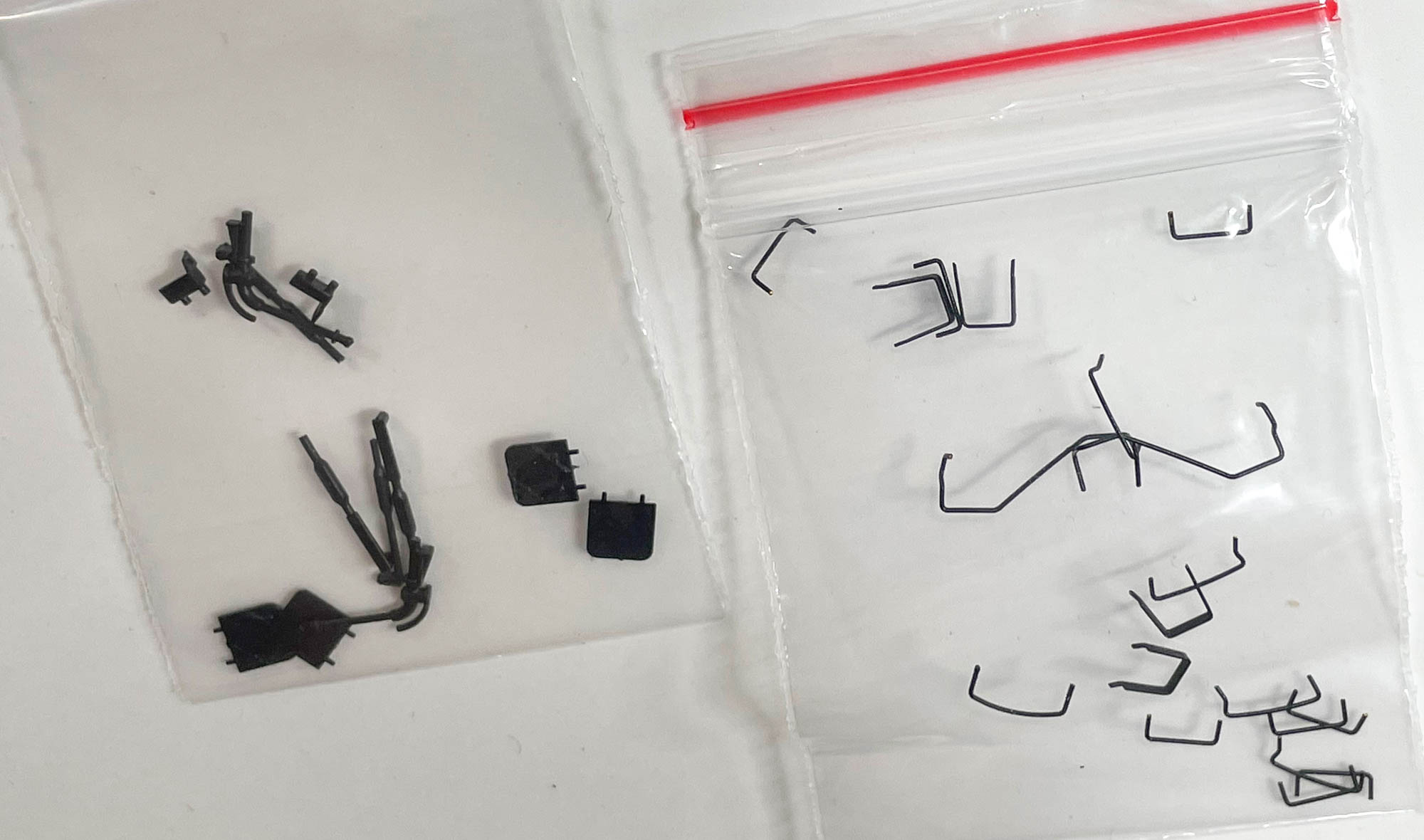
The details to be added by the modeler, including grabs, uncoupling devices, placard holders, etc., are secured separately in tiny zip bags for safe keeping. The placard holders match the style used on almost all UTLX tank cars, a nice touch

I will be detailing and lettering this model over the coming months using the decal set from National Scale Car. Follow this blog to be notified of updates.

Friday, January 20, 2023

Union Tank Line Type X Tank Car Parts from Shapeways

San Diego, California, December 4, 1954, Col. Chet McCoid photo, Bob's Photo

I have been intending to create this post for a long, long time. That time is finally now. For as long as I can remember, Model Die Casting (MDC; now part of the Athearn universe) has offered a ~6,000 gallon "old-time" tank car. The rivets are too diminutive and there are some in places where they shouldn't be, but that is pales in comparison to the big chunk of white metal that doubles as the underframe and running boards. An enterprising seller on Shapeways decided to rectify that major shortcoming. The seller, Austin Rail Products, offers 3D printed underframe and running boards to turn the model into a quite passable UTLX Type X tank car (for those looking for more information about UTLX and its fleet, the "bible" authored by Steve Hile is currently being reprinted with an estimated availability date in early February.)


Excepting the other shortcomings of the MDC kit as well as the aftermarket detail offerings to rectify them, the focus here is on the two parts. The underframe is well-rendered an is a perfect fit to the bottom sheet of the tank. It will be a simple matter to glue it in place at the tank saddles and the tank anchor. There are some 3D printing artifacts, but in all honesty, they are not aggregious and the underframe is a place where they will not detract in a measurable way. In terms of the underframe itself, it is an excellent rendition of the Type X underframe, with bolster castings capturing the open shape of the prototype. The one major obstacle to overcome is equipping the car with a coupler. The part is not designed with a specific HO scale coupler offering in mind (at least I cannot ascertain this) so I will need to devise a creative solution to add couplers.

Like the underframe, the running boards are a perfect fit to the tank sheets. The creator obviously spent time to ensure that they would be a "drop fit" addition. The supports ("brackets") are well-detailed and fit against the tank sheets perfectly. Being running boards, there is little else to say!


As the scope of this model is more than just a simple swap of a few parts, I will develop several posts to highlight details on the prototype and how to replicate them in HO scale, using commercially available parts as well as some scratchbuilding and/or modification. I look forward to this journey!

Saturday, July 23, 2022

USAX (ex-US Quartermaster's) USG-A 'Emergency' Tank Cars - Part 2

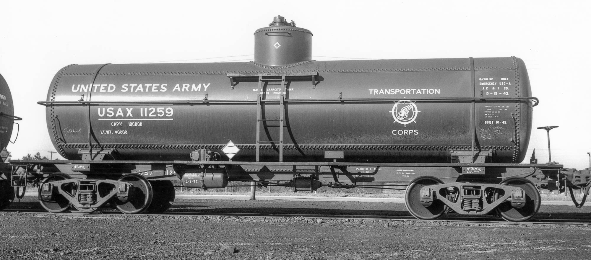
Ft. Bragg, NC, March 27, 1959, Col. Chet McCoid photo, Bob's Photo

In the first post about the USAX (ex-US Quartermaster's) USG-A 'Emergency' Tank Cars, I touched upon the prototype and the first steps in using the Tichy tank car kit to replicate them in HO scale. Here is an update on my progress.

Unlike the SHPX USG-A Emergency cars, these cars built for the US Quartermaster had welded center sills, similar to an AAR underframe, with two zee sections welded along an adjacent edge. The tank anchor was riveted directly to the "face" of the center sill sections. See the detailed photo for reference. Now, I could lie and say that I figured this all out right from the start... but that's not the case. At first, I assumed that there was a cutout in the top cover plate of the center sill to accommodate the tank anchor. Closer examination of this image and the ones in the Mainline Modeler article (Thornton Waite, January, 2006) revealed otherwise. Also, AAR underframes don't generally have top cover plates. So I reacted midstream.


What follows is a mostly blow-by-blow of my steps, including several errors! I removed the part of what are essentially "rests" from the bottom of the tank. These are shown in red in the photo above. I have included the after view, as well. Neatness isn't paramount as these are well-hidden by the tank. 
Before, bottom and after, top

I also modified the tank saddles by filing them to create a more sloped outward facing surface where I will add styrene to connect to the body bolsters. That even included removing part of the outermost wood block on each side of the saddle. However, only a very keen observer will notice that on the finished model. See photo


The tank also had sheet reinforcements at the saddles that were welded to the bottom tank sheet (see prototype closeup at the top of the series of photos above.) I replicated these with 0.005" styrene, 0.40" wide and sized to run essentially from one side of the tank to the other, between the saddles. Lightly bend these pieces of styrene to create a "curl" that matches the bottom tank sheet (I didn't and wish I had; profit from my error!) I taped the center sill/end sill to the tank at the location it would be when finally secured. I then carefully slid the 0.005" styrene between the bottom of the tank and the saddles and moved one into the "perfect" position before carefully tacking it in place with liquid styrene cement (make sure to only tack in place and don't glue the saddles in place; just glue these sheet reinforcements in place.) After the first is tacked in place, repeat the process for the second. Let these set for a little bit (~15 minutes) and then remove the center sill/end sill and apply more liquid cement to secure the styrene and ensure it follows the contours of the bottom tank shell. Note: the rectangular piece in the center of the tank in the photo directly above is/was part of the anchor/center sill cover plate in the kit. It was not used in the model.


I attached the center sill/end sills assembly to the tank, as shown above. First, I glued the saddles to the styrene tank reinforcements. Next, I wanted to add something between the top of the center sill and the bottom of the tank, knowing it would be hidden by the actual anchors once they are added. The purpose is two-fold: add another point where the tank is attached to the underframe and maintain the spacing between the tank and the center sills. I chose to use strip styrene and through trial and error arrived at a piece of styrene 0.045" x 0.080" created from 0.080" strips of 0.015" and 0.030" glued together. Why so precise? If the strip isn't the right size, the center sills will appear to bow or curve up or down (closer or further from the bottom sheet of the tank) which would look highly unrealistic. The strip is highlighted by the yellow arrow in the upper of the two photos directly above. The significance of the red arrows? To highlight my biggest faux pas (so far) on this project. In the upper photo, the red arrows point to the flanges on the top portion of the center sills, which should not be present on a car with zee section center sills. After realizing my error, I carefully removed most of the flanges by scoring and snapping and a little cleanup. Look closely in the lower photo and you will see there are small amounts remaining. These are where the running board supports meet the center sills. I will clean that area up after the supports are added.


Next, I added the tank anchor and center sill flanges. The anchor was fashioned from two pieces of strip created from 0.005" styrene. The one attached to the "face" of the center sills is 10 scale inches wide. The curved cutouts at the end were simulated by using the male portion of a punch and die tapped at an angle, although careful use of a hobby knife could yield similar results. The long portion that abuts the bottom of the tank is seven scale feet long. The upper photo of the two directly above shows the model with the 10-inch strip added. Next, I added a three-inch wide strip, again from 0.005" styrene, abutting the 10-inch strip but attached to the surface of the tank. Note that I angled the corners, common on the flanges attached to the bottom tank sheet. I added 1x6 styrene strips to the center sills to complete the lower legs of the zee sections. Also of note are the areas on the underside of the running boards where I removed strip material. The photo directly above illustrates these details including callouts (the dotted line was added for effect.) That's where the model stands as I type this. More to come in a subsequent installment...

Tuesday, May 3, 2022

USAX (ex-US Quartermaster's) USG-A 'Emergency' Tank Cars


In 1942-3, American Car & Foundry built Emergency-design, designation USG-A tank cars for SHPX leasing services as well as for the US War Department, Office of the Chief of Transportation (US Quartermaster) under USQX reporting marks, series 11168-11178, 11200-11309, and 11311-11475 (four cars in 11168-11178 had two domes/two compartments). The cars used contemporary underframes with World War One era tank designs. The late Richard Hendrickson authored an article about the cars in the October, 1990, RailModel Journal, available online via this link.

Modelers are fortunate to have excellent HO scale versions of the tanks from Tichy (originally Gould.) Many (if not all) of the SHPX tanks were scrapped/recycled in the postwar era, with the underframes being re-used, but the USQX cars soldiered on under USAX reporting marks (there were also Canadian prototypes, profiled by Russ Pinchbeck, including modeling, in the July, 2002, Railroad Model Craftsman.) There was also an article about the USAX cars by Thornton Waite in the January, 2006, Mainline Modeler. That is the inspiration for this project.

I have a seemingly great number of freight car projects nearing completion, so in between those painting, decaling, and weathering duties, I have dabbled a little in this project. I started with a Tichy tank car kit with a 54-inch dome width. There are several modifications to arrive at a USAX prototype, including modification of:

  • the location of the safety valves (I added other details, too)
  • the tank anchor
  • the tank bolsters
  • the underframe


Thus far, I have made changes to the dome. The overlap of the tank shell on the dome is quite simple, to the point that it seems to be almost missing. I removed the rivets and added a strip of 0.005 thousand styrene, blending it into the face of the dome at left, and leaving a sharp edge at right, as shown in the photo directly above. I will (re)apply rivets to the dome in the appropriate locations.


I also removed the safety valve locations, reserving the "center" of the valve locations. I puttied and sanded the old locations and then added discs to the top of the dome for the new locations, as shown. I then added the valve "centers" that had been salvaged, being careful to orient them so the top was "level" as these had gently sloped (actually curved) bottoms so that the top would be level. Somewhere in all of this, I added the dome to the tank and secured it with solvent cement.


Next up in this series: the tank anchors and body bolsters. I have been working on artwork for USAX/US Army Transportation Corps lettering...

Sunday, December 29, 2019

Shell Chemical Tank Cars - colors?

Toronto, Ontario, Jim Parker photo
Shell Chemical (as well as Shell Oil) had a West Coast facility based in Martinez, California. The area around the Carquinez Strait was a hub of petrochemical businesses and still has a large number of operations. I have an interest in modeling a couple Shell Chemical cars, including one in the scheme shown on these two cars. However, not having any color photos, I would be guessing at the scheme. I can discern (or imagine?) a difference in the hue of the reporting marks and other stencils contrasted with the "SHELL CHEMICAL" lettering. It seems likely that the name is red while the other lettering is black. The color of the tank is the other question. It appears to be gray or silver/aluminum. I am hopeful that someone can offer some definitive information, but my best source so far is the photo of a Strombecker kit produced in 1948 (see bottom). The tank wrapper in the kit has a gray tank with black stenciling and red company name. Given the kit's contemporaneous manufacture with the existence of the prototype, it seems highly plausible that the producers of the kit were basing the scheme on primary source material, meaning they might have actually viewed the scheme in question or had gathered material directly from Shell or GATC to aid in accuracy. In the absence of other information, the Strombecker model is my best resource.

Note that the two cars are both General American designs. The car shown at top, SCMX 840, is a GATC "Type 30" design, of 8,103 gallon capacity, built in November, 1936. SCMX 2061, below, is an interesting car. The insulated, pressurized ICC 105A 300W tank was built in May, 1943 and is in service hauling Anhydrous Ammonia. It had a capacity of 11,161 gallons. The frame is a GATC postwar design and was likely married to the tank in September, 1950, assuming that occurred when the car was last reweighed in September, 1950.


Pittsburg, California, October 26, 1952, Col. Chet McCoid photo, Bob's Photo


Wednesday, November 20, 2019

Transition Era Texas Oil (Texaco) Tank Cars - Part One


In 1935 the sizeable Texaco tank car fleet, just under 6,000 cars strong, was sold to General American and leased back to Texaco. The reporting marks remained unchanged, using T.C.X. However, throughout the 1940s, as cars were repainted, the billboard "TEXACO" scheme was abandoned in favor a simple black car with only the basic information, like that shown on TCX 6852 shown above (Hamlet, North Carolina, October 14, 1951, Col. Chet McCoid photo, Bob's Photo.) 

TCX 6852, built in April 1929, also illustrates a couple of other details worth noting. The AC&F 10,000 gallon Type 27 tank cars built in the late 1920s had shorter, fatter tanks, similar to those of the Type 21 design, albeit with three instead of four courses and four tank bands. TCX 6852 is an example of such a 10,000 gallon Type 27. After about 1930, 10,000 gallon Type 27 tank cars featured longer, narrower tanks with only two tank bands. Another interesting detail are the Dalman two-level trucks without Barber lateral motion devices.


TCX 7892, built in May, 1927, is another AC&F 10,000 gallon Type 27. It illustrates the billboard scheme, with silver tank and black stenciling. I also included this photo because the details of the Texaco dealer (along with the Signal dealer at left) are notable for modelers, including the pumps, barrels, sign, etc. Will Whittaker photo at Woodland, California, December 17, 1939.


TCX 4154 also effectively illustrates the simplified post-GATC takeover scheme. It was built by Petroleum Iron Works in May, 1927. Hamlet, North Carolina, October 14, 1951, Col. Chet McCoid photo, Bob's Photo


This last photo is included because it illustrates an interesting Texaco detail stenciled on the ends of cars. Note the rectangle at the right of the tank head (end) containing "F" over "10". TCX 6852 above has "R" over "10", TCX 4154 has "R" over "8" and TCX 7892 also has "R" over "10" on the head. The numbers almost certainly refer to the tank capacity with "8" = 8,000 gallons and "10" = 10,000 gallons. While it is supposition the "F" might refer to fuel while the "R" could refer to refined products. No doubt, one of you can offer some additional details and/or corrections. Photo by Esther Bubley in Casper, Wyoming in 1948.

Information about decals for the GATC era to follow in Part Two

Monday, November 18, 2019

The Anatomy of a Tank Car - General American

The following pamphlet is something that I have in my collection of various materials. As noted from the cover letter, it was sent to Franklin Creek Refining of Franklin, PA, by Garland Smith, Manager, Repair Sales, of General American Tank Car. The photo above is a GATC Type 30 tank car, like the type profiled in the pamphlet. Photo from my collection