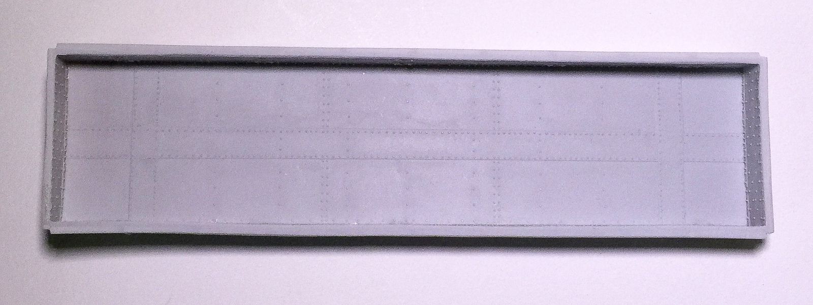
Showing posts with label Southern Railway. Show all posts

Thursday, July 9, 2026

Southern Railway Postwar AAR Box Cars - an extremely interesting quirk


As an expansion from my previous post, the Southern purchased 1,000 Postwar design AAR box cars from Pullman-Standard between 1946-1947, Lot 5855. The most visible details were 8-foot door openings, not unheard of at the time, but not all that common, either, and their Superior 7-panel doors or Improved Youngstown doors with 6-6-5 arrangement (top to bottom.) Other details included prominent push pole pockets and specialties as noted in the table below.

Series StartSeries EndSide sheathingSubsidiaryHand BrakeRunning BoardDoors
330000330499IrregularNO&NEMinerMorton Open GripYoungstown
2300023241RegularSouthernUniversalMorton Open GripYoungstown
2324223268RegularSouthernUniversalMorton Open GripSuperior
2326923299RegularSouthernUniversalMorton Open GripYoungstown
2330023472RegularSouthernUniversalMorton Open GripSuperior
2347323486RegularSouthernUniversalMorton Open GripYoungstown
262000262049RegularCNO&TPUniversalMorton Open GripYoungstown
307025307027RegularAGSUniversalMorton Open GripYoungstown

One interesting quirk that I noticed in photos years ago, but hadn't researched thoroughly was that 500 cars had a highly unusual, if not unique arrangement of side structural posts (zee bars where the side sheathing panels overlapped and were riveted.) On 500 cars, the structural posts were marginally closer together (3'0-1/2" vs. 3'1-7/8" on a standard arrangement) and an additional structural member was added extremely close to the adjacent end, necessitating an additional row of rivets close to the ends and corner posts. I have not seen this feature on any other cars and have no documentation as to why it was done. The only reason for this arrangement that makes sense to me is that four of the panels on either side of the door were generated from tooling for a car with a 7-foot door opening (the edges closest to the car ends were crimped to overlap the next panel) and then the last panel on each side, adjacent to the ends, which did not have a crimp (it was just sheet/plate steel) was made wide enough to span the leftover distance. A plausible (yet thoroughly speculative) reason is availability of such side sheathing panels when the first cars were built beginning in 1946; maybe panels for 7-foot door opening cars were already being cut and pressed for the Nickel Plate order, but presses for 8-foot door opening sides were not tooled yet. This rationale is a weak explanation for the presence of the zee bar structural member 6-7/8" from the corner post. Nonetheless, it results in an extremely cool feature if you're a freight car geek, like I am. Click on the photo to see a larger view


This photo of Southern 23000 illustrates another interesting detail that I have only found on this car. It was equipped with roping staples at each bolster. I am unsure if there were other cars wit hthese, but it is noteworthy. I could find no reference to it in the Southern book*.


There is (was) an incredible reference for Southern box cars, Southern Railway Equipment Drawings and Photographs, Volume 1, Book 1, 40' Steel Box Cars, George Eichelberger, Southern Railway Historical Association, 2004

Wednesday, July 8, 2026

Good times, great oldies... Forty-foot Postwar AAR Box Cars


This Georgia car is a decorated Branchline kit, save for a Southwest Scale Improved Youngstown doors with 6-6-5 (top to bottom) arrangement of corrugations and matching paint on the door and Ksto ASF A-3 trucks

Way back in the early times of Speedwitch over 20 years ago, I had offered several sets of parts to replicate the various details and nuances of forty-foot Postwar AAR box cars, using the fine Branchline kits as fodder. They were a fun way to model the distinctive details of these cars. Anyway, I stumbled across a tote of parts in the barn yesterday and it had various bits for the Santa Fe's Bx-44 cars, with their distinctive interim Improved Youngstown doors. That also got me thinking about the cars in general. What a fun ride they were. Here are some pics of those cars with notes about some of the details.


The Santa Fe's 500 Bx-44 box cars were distinct for their interim Improved Youngstown doors, with wide panel overlaps. The cars also had Pullman-Standard "notched" tabs below the side sill and a flattened area on the end corrugation where the hand brake housing was mounted.


The Wabash continued their use of full-length side sill support sections that spanned the bolsters, as also added to earlier Modified 1937 AAR box cars. They also used pressure head cylinders with integral lever brackets, Superior seven panel doors, and Wine style ladders, among other specialties.


The Southern and subsidiaries purchased postwar AAR box cars with eight-foot door openings with either Superior seven-panel doors (shown) or Improved Youngstown doors with the 6-6-5 corrugation arrangement as well as Pullman-Standard "notched" tabs below the side sill. PS - the washout on the Southern medallion is what happens when you accidentally use solvent cement as a decal softener!


The Pittsburgh & West Virginia cars had Improved Dreadnaught ends with an "abbreviated" (shortened) top main rib and prewar-style Youngstown doors plus Wine-style ladders. The repainted version above was modeled by the late Paul Lyons and the model below shows an as-built car


The Erie purchased 1,200 cars that also had an abbreviated top rib on the ends and prewar-style Youngstown doors, plus Universal Rotary Type brake adjusters and a variety of hand brakes, trucks and running boards


The Louisville & Nashville has distinctive cars with three door styles (prewar Youngstown, 6-6-5 Improved Youngstown and seven-panel Superior) and ends without any lower corner additions below the end sills

These were a lot of fun to create and are highly illustrative of how different "standard" cars can be

Friday, February 28, 2025

Something a Little (maybe not so little) Different


Al Armitage photo, Ron Morse Collection

One of the nice things about Springfield is catching up with friends.  I had a chance to see Scott Kritzky and Terry Van Winkle. Awhile back, I had offered mostly encouragement, but also a bit of prototype reference material to Scott for one of his projects. He shared the fruits of his labor with me at Springfield. He and Terry have produced a beautiful set of O scale ends for the Southern's 'SU' thirty-six foot truss rod box cars. Having them eliminates the most difficult obstacle to modeling one of these numerous cars. Well done and I can't wait to see what they conjure up next, perhaps even in a smaller size... maybe 1:87.1?!

Some of these cars also enjoyed a renaissance on the Lancaster & Chester in the postwar years

All blemishes, smudges, scratches, etc., are my fault entirely and not a reflection of the quality of these parts!


Friday, December 13, 2019

Late Steam Era 36-foot Box Cars

Jim Gerstley
Several months ago, I mentioned that I would post a list of 36-foot box cars that would be useful prototypes for late 1940s to early 1950s modelers (meaning that these cars were still operating in reasonable quantities, either in gross numbers or as a percentage of the road’s fleet.) Without much fanfare, here is the list, along with some photos, and HO scale model references where known.


Al Armitage photo
*Canadian National Dominion/Fowler Patent single sheathed box cars - the CN's cars including subsidiaries are too numerous to chronicle in a sentence; it is sufficient to say there were over 33,000 cars with many subtle detail differences; HO scale models from Speedwitch K104 kits (five-foot door opening), Westerfield, True Line Trains/LifeLike Canada, AccurailMainline Modeler, November 1985

Roseville, Calif., Oct 24, 1952, Col. Chet McCoid photo, Bob's Photo
*Canadian Pacific Dominion/Fowler Patent single sheathed box cars - like the CN, the CP had a massive fleet, with over 33,000 cars for itself and subsidiaries; too many to delineate in a sentence or paragraph; HO scale models from Westerfield, Accurail (six-foot door opening only); Mainline Modeler, June 1985

George Sisk photo, Charles Winters Collection
*Other Dominion/Fowler Patent single sheathed box cars, including Erie, NYS&W, NC&StL, PGE, Wabash, Soo, and others - Westerfield, AccurailMainline Modeler, April 1986

Delaware & Hudson double sheathed box cars profiled through the link included herein - models may be kit-scratchbashed or old Funaro & Camerlengo kits; Railroad Model Craftsman, November and December 1987

Bob's Photo
Erie single sheathed box cars (different from the Erie's Fowler/Dominion cars and more numerous in the late Steam Era). These cars were built by Standard Steel in 1921 and assigned to 93000-93999. They featured hat section pressed steel structural members as shown on Erie 93132 above. - no models at present

Harry Zillmer photo
Illinois Terminal 8100-8199 series single sheathed box cars built by Mt. Vernon in 1928. Note the Dalman Two-Level trucks (without Barber Lateral Motion devices) - Sunshine Models kits

Paterson, New Jersey, ca. 1947, Sirman Collection
Louisville & Nashville double sheathed box cars. Over the years, the Louisville & Nashville had thousands of such cars, with many subtle and not so subtle differences in characteristics. By the twilight of Steam, they were concentrated in two series: 8000-8999 and 10000-11999. Note the extensive damage to the door frame and roof at left edge of door in photo above - Sunshine Models

Missouri Pacific Lines double sheathed and rebuilt box cars. MP had cars as shown above well into the late 1940s and 1950 with many rebuilt into distinctive all-steel cars like MP 120050 shown at the top of this post - Sunshine Models; Railway Prototype Cyclopedia, Vol. 14.

Bob's Photo
New York Central System (NYC, B&A, P&LE) double sheathed box cars - Funaro & Camerlengo (general site link - search by road for specific kits), Accurail. F&C had a kit for this B&A car with Dreadnaught ends (I had one and gave it away to a friend recently as I have no need for more than one B&A car and my one is a USRA-design steel car.) 

Al Armitage photo
Southern (Mobile & Ohio and Lancaster & Chester) double sheathed truss box cars. These were incredibly numerous (almost 15,000 cars) and some of the last truss rod cars built - WesterfieldFunaro & Camerlengo; Railroad Model Craftsman March 2004
*Russ Pinchbeck and the late Stafford Swain presented a clinic about the Fowler/Dominion cars on the RPM circuit circa 2003 and included a detailed handout.

Eric Hansmann's blog Notes on Designing, Building, and Operating Model Railroads has much good information about 36-foot cars (particularly the NYC System cars produced by Accurail) as he is a 1920s-era modeler and his need for these cars is obvious!

Below are a few models. From top to bottom, Westerfield, Speedwitch, Westerfield


Sunday, October 14, 2018

Southern Railway Low-side Gondola - completed finally


I find it hard to fathom that it has been about two-and-a-half years since I posted about building this car. I finally got around to dusting off the cobwebs and finishing the model. The main stumbling block beyond time was the hand brake. The prototype used a Universal Multi-power hand brake, with the gearing mechanism contained inside a housing mounted below the end sill. I spent many free moments noodling how I would replicate that feature (when I made the patterns for this model, I never even considered it… how time changes things!) I have included a prototype photo below for reference (click to enlarge).

I settled on the solution illustrated in the graphic. Since the overall shape of the prototype’s housing was roughly segments of two differently-sized circles, that’s the approach I decided to follow. I punched discs from 0.020" styrene. The larger disc was created using a Waldron punch and die set while the smaller used an RP Toolz set. Portions of the two discs were combined to create the housing.


I found it easiest to integrate the entire assembly after adding the brake step to the model. The step, with hole for the brake shaft, was “rigidly” attached to the end. I added the housing using a 50/50 mix of Goo and MEK. This allowed me to prod and move the housing into position, with 0.020" wire in place (note that the wire on the bottom of the housing is a separate piece of 0.015"; the two were of different diameters on the prototype, too.) Once I was satisfied, I added some ACC to the housing — end sill joint to firm things up.


The bottom part of the housing was fashioned from pieces of 0.004" brass, cut into strips of appropriate width. As on the prototype, the bottom portion of the shaft nested in this arrangement, so I drilled holes in the straps to accommodate the 0.015" wire. This is partially obscured by the uncoupler lever rod so it likely adds little to the overall appearance of the model, but it is a feature I wanted to replicate so that I can make it for future projects.

The trucks also include a slight modification. The Tahoe Model Works Buckeye 50-ton trucks (TMW-106/TMW-206are a fairly solid match for the prototype’s trucks, but the truck bolster includes a vertical web through the center of the outside portion of the bolster casting. I replicated this feature by adding 0.010" strips into the center of the Tahoe bolsters. See the photos of the stock truck via the link above versus one on the model shown here.

I blasted all wire, metal, engineering plastic, and rubberized (Hi-Tech angle cock—air hoses) surfaces with 220-grit aluminum oxide. This created a surface conducive to good paint adhesion. I applied a coat of Tamiya Light Grey followed by Tamiya black, lightened slightly with grey. The black dried to a glossy sheen, perfect for applying decals. 

I lettered the model using the kit decals. At the same time, I added several chalkmarks to each side. These would be over-weathered, making them appear like older chalkmarks, to contrast with “newer” ones to be added post-weathering. I did not apply the reweigh, repack, and brake test stencils, as these would be added after the first application of weathering. These decals were sealed with a coat of Tamiya clear flat.

The weathering was applied in several steps. The interior of the car received a heavy application of Bragdon’s powders dark rust. Over this, I added a layer of PanPastels dark Payne’s Grey followed by an application of PanPastels dark umber over the entire model. On the trucks, I highlighted the truck springs with a rust shaded colored pencil. I then added the PanPastels Payne’s Grey and dark umber followed by some Bragdon’s soot grey. All of these powders were sealed with a coat of Tamiya clear flat.

I forgot to mask the areas where I would apply the reweigh, repack, and brake test stencils. This meant that I had to do the reverse and add fresh black paint to those areas. The reweigh and brake test stencils on the model would be applied to represent approximately three year old stencils while the journal repack would be less than a year old. Consequently, I created fresh paint rectangles for all three. However, for the journal repack rectangle I cut the rectangle from a solid piece of masking tape. I painted the area inside the opening of the masking tape with fresh black paint (I did the same for the reweigh and brake test rectangles, too.) For the journal repack rectangle, I then covered it with the “center” of the masking tape (the part that had been removed).

To the appropriate freshly paint areas, I added stencils corresponding to the reweigh location and date and brake test location and date. After application of decal setting solution, I airbrushed a coat of clear flat. I removed the tape over the repack stencil “rectangle” and added another round of PanPastels raw umber to the exterior car body followed by a coat of Future floor polish, creating a gloss surface. I added another round of chalkmarks plus the journal repack stencils. I applied a final coat of clear flat to the exterior of the car body.

Finally, I added the last details. I added wood and scattered bits of coal to the interior of the car to represent dunnage and debris from previous loads. I polished the treads of the wheelsets and screwed the trucks to the car body. Small pieces of paper were affixed to the route card boards with canopy cement to represent routing instructions (photo of finished model taken before these bits of paper were added). Southern Railway 55542 was ready for service.

Sunday, December 4, 2016

Southern gondola, part two

A long time ago, I posted about some tips to build the Speedwitch Southern gondola kit. I have done some additional work on the brake gear and want to show how I tackled things. I tend to deviate from the instructions, even on my own kits, and this car is no exception. The details follow. First, I do not have a brake arrangement for this car. I do for a similar series of Southern low-side gons built at about the same time. I used that along with prototype photos to arrive at what you see here. I cannot declare that it is 100% accurate, but it works for me.

I added the main three components: cylinder, reservoirs, and AB valve (pre-drill these first if you will be adding wire to simulate the piping). The cylinder uses a resin bracket and was attached to the face of the center sill. The AB valve was attached to a "platform" that spans the two cross members. The reservoirs were secured with brackets created from 1x4 and 1x12 strips that simulate the steel parts to which the reservoir lugs were bolted. I added nut-bolt-washer (NBW) and rivets (from an Athearn snow plow, although Archer rivets would do, as well.)

With the main components in place, I used 0.010" wire to represent the piping between the AB valve and the cylinder and reservoirs. This required some bending, fitting, and cutting to get things right, followed by securing the wire in place with ACC. I use fine, round-nose beading pliers to make these bends. With the main piping in place, I added the dirt collector to the AB valve, after first drilling it to accept the pipe from it to the train pipe. This pipe is larger, simulated with 0.015" wire, meaning the corresponding hole in the dirt collector needed to be larger. My technique is to first drill a hole with a no. 79 bit and then "open" the hole with a no. 77 bit. As I did not model the actual train pipe, the 0.015" wire runs from the dirt collector to the floor of the car, as shown.


With the piping in place, I added the brake levers and rods. The levers were created from 1x8 strip styrene, trimmed to shape using a single edge razor blade. The main lever rests in the clevis (part no. 29 on the Tichy AB brake set) extending from the cylinder. The clevis opening is actually about 0.020" wide so I always add a little .010x.030 shim at the end of the lever so that it nestles snugly into the clevis. For the bracket for the dead lever, I used a piece of leftover flat brass from an etched metal parts set. I created a u-shaped end to accept the brake lever and added two bends to allow the lever to be offset from the center sills once the bracket was glued to the face of the center sill.


With the levers in place, I added the brake rods. My technique is to add a Tichy turnbuckle to the end of a piece of 0.012" wire. One end of the turnbuckle is removed so that the resulting piece looks like a clevis. I slide these clevises over the 1x8 styrene levers and mark the wire to create bends and measure distances for cuts as I go. The turnbuckles "hold" the wire in place over the levers, allowing me to make my measurements for bends and cuts. I use a black Sharpie to mark where to bend or cut the wire. Once all the bends are made, the rods and turnbuckles are secured with ACC. Note that my brake rods are secured into the bolsters. Also, for these bends, I use a pair of beading pliers with "flat" jaws that result in sharp bends. More round, "radiused" bends look right for piping, but for the brake rod wire, a sharp bend works much better.

That's it. The next post about this car will show the finished model. The photo included here is of a finished model I built years ago, although it is the same car from the same kit. Also, a shameless plug: there are six of these kits left and once they're gone, this one will be closed out for good. So if you'd like one, navigate to the Speedwitch site and get one before they're gone.


Wednesday, February 24, 2016

Building the Speedwitch Southern gondola

The gon as viewed from the underside with strip added and underbody glued into the car body
The Southern gondola kits were my first efforts when I launched the resin portion of Speedwitch. To say that I tried to have my cake and eat it, too, is an understatement. I hated gondola models where there was a sacrifice in that either the interior side walls weren’t tall enough relative to the prototype or there wasn’t anywhere to conceal some weight. I was determined to make a car where the interior was “the way it should be” and you could still stash some weight. As with most open top scale models, something had to give. In this case, the “give” was the depth of the underframe. I purposely made the bolsters, crossbearers, crossties, and center sills shallower than the prototype in order to achieve a prototypical car interior and have somewhere to put some weight. That also meant that the coupler pockets were forced to sit right on the underside of the gondola floor, in a “cut-out” in the underbody. This also makes it a challenge to secure the coupler pockets. In retrospect, I probably bit off too much. I am certain there are many out there who are still trying to figure out how to build one of these successfully. What follows is what I hope will be a step-by-step guide to augment the kit’s instructions and explain one person’s path to building the car into a beautiful and operable model.
The interior with the floor attached
The initial step is to clean up the main body casting, comprised of sides and ends. My course of action was to rub it back and forth on a sheet of 220-grit sandpaper on a flat surface. I held the casting in between thumb and forefinger and rubbed the casting parallel to the line of the surface I was holding, switching the places I was holding frequently to avoid removing too much material in any one location. By “parallel to the surface I was holding,” that means that if I was holding the car side, I moved the length of the car side back and forth along the sandpaper. Conversely, if holding the end, I moved the length of the end back and forth across the surface of the sandpaper. In a fairly short amount of time, the casting “flash” inside the top of the car body became thin enough to flick away in most places. In those areas where there was still a little material holding the flash in place, I held the casting in that specific area and moved it across the sandpaper as described previously. Once the excess material had been removed, I cleaned up the top edges of the car with a sanding stick (read about sanding sticks by clicking.)
An additional view with the underbody added and the strip styrene visible at the edge
The first snafu involves the floor of the gondola. This is the part with detail on its surface that fits inside the car body and faces up when the car is on the rails. It is slightly too long (this is okay) and slightly too narrow (not okay.) It must be made marginally wider. To do this, I added 0.020” x 0.020” styrene strip to the edges (the long edges) of the casting. This was actually really easy to do. I simply laid the casting on a flat surface with the styrene strip butted against it and held in place by my finger and added a little ACC along the length using a straight pin as an applicator, moving my finger as I went, to expose the areas I hadn’t attached. It took less than five minutes. Work in small drops rather than big gobs and there will be no ACC mess or parts stuck to your work surface. It doesn’t hurt to keep checking as you go, though, to make sure your part isn’t attaching itself to your work surface. With the styrene strip added, the casting is ever so slightly too wide. A few (and I mean a few) passes of the casting over sandpaper on a flat surface should narrow things enough to fit inside the car body. To do this, hold the casting on edge and run it over the sandpaper. I always run it the same number of passes in one direction, the other direction and then flip and do the same for the other side. It’s not entirely scientific, but it does remove roughly the same amount from both sides. Do the same to shorten the ends of the casting and it should fit snugly, but not tightly, inside the car body. It fits inside the lip that is in the car body, meaning the edges of the casting you just narrowed will not be visible once the floor is glued inside the car body, if viewed looking “into” the car body, as you would if it were on the rails.
From the top, the undeframe, car body and underside of floor, and the lead weight, all with the Goo and MEK mixture added to the surfaces
Gluing the floor inside the car body is a relatively easy process. Put the car body casting on a flat surface upside down, with the top edges of the car body in contact with the flat surface. Place the floor inside the car body. You should be looking at the undetailed (“underside”) surface of the floor. If you are looking at the rivets, stop and reorient the parts. To glue the floor into the car body, there are two key things to consider: 1) work in small increments, rather than trying to glue it all at once and 2) a light pressure is all that is needed; a death grip will surely create distortions in your body casting meaning either the sides will be grossly bowed or you will induce “torque” along the length of the car body, resulting in a pronounced twist to the body. Gently push the floor into the car body so that the floor rests inside and snugly against the lip in the car body. I found it easiest to start at the center of the car and then work towards one end followed by the other. With light pressure, gently press the car body together with thumb and middle finger while applying slight pressure with the index finger to keep the floor pushed into the car body. The thumb and middle finger should be applying pressure near the edge of the car body that is closest to you (and where the floor casting is contacting the car body), not the edge that is touching the flat surface on which you are working. Applying pressure where the car body is resting on the flat surface will cause the car sides to bow, angle or cant inwards. Gentle pressure using this three-point approach with thumb and two fingers applies all the force necessary to keep things in place while you add the ACC. Add some ACC where you are applying the pressure to the joints on both sides of the car body (at the places where both thumb and middle finger are holding things together). Hold until the ACC has set up the joint. Repeat at several points until the floor is secure from the middle to one end and then repeat from the center to the other car end. As you work, make sure that the floor is nested all the way into the lip in the car body. This is your one chance to get this correct. Go slowly, checking your progress frequently. Once you have tacked everything in place, go back and add ACC along the entire floor/car body joint. If all is well, you should have the “bones” of a gondola in your hands!
The car body with weight attached and awaiting addition of the underbody casting
The next series of tasks involve addition of weight between the floor and underbody followed by gluing the underbody into the car body. For the weight, I have a large roll of 0.020” thick sheet lead that is perfect for this car (I believe it is some type of flashing for use in the roofing industry). I cut a piece of lead to fit exactly into the cavity under the floor, minus the notched areas where the coupler boxes would be located. I “painted” the underside of the car floor and the top of the weight with a mixture of Walthers Goo and methyl ethyl ketone (MEK). The MEK makes the Goo less viscous and able to be brushed on to surfaces. Once the Goo had thoroughly dried, I dropped the weight into the cavity and carefully pressed the two surfaces together, between thumb (on the lead surface) and forefinger (inside the car body). Don’t put the car body upside down on your work surface and just push on the underbody. You could damage or deform the car body. Use the thumb-forefinger technique described above as it places pressure only on the floor and underbody, not the car body. I brushed the Goo on to the still exposed lead surface and the “top” of the underbody. Once again, I let the Goo dry before adding the underbody and again pressing the surfaces between thumb and forefinger. This completed the basic assembly of the car body.

The modified coupler boxes as described in the text
The coupler and "draft gear" as attached to the model
The next task was the addition of the couplers. I used Kadee no. 153 scale couplers in the Kadee-supplied coupler boxes (“draft gear”) modified as shown. The no. 153 coupler is the same as the standard no. 158, but with a shorter shank length that was better for this car. The basic modifications included shortening the main half of the coupler box (the piece with the circular post and the “sides” of the coupler box) to butt against the inside of the end sill, and narrowing the front lip of the other half of the coupler box to fit between the draft gear opening of the car body’s end sill. Lastly, I added bits of HO scale 1x4 strip styrene to complete the “sides” of the coupler box that extend past the draft gear. The next challenge to overcome involved actually securing the coupler boxes to the car body. After some deep thought, I came up with the following plan: I would run a piece of 3/32” styrene tube through the post of the coupler box and, after drilling a hole in the floor, straight through the floor of the car. Yes, it meant a piece of styrene rod protruding from the floor of the car and subsequent sanding and cleaning up of the car floor after my “surgery”. The converse, though, is that I had a secure means to attach the couplers, beyond just gluing them (and we all know how that ends up: a coupler and lid sitting somewhere on the layout with half a train sitting uncoupled behind the coupler!) After all, the styrene rod isn’t moving and it has a hole that can accept a screw to secure the coupler boxes. That’s what I did. After everything was in place, I added a small bit of styrene rod into the center of the styrene tube visible on the top of the car floor (the hole in the tube on the underside of the car needed to remain clear to accept a 0-80 screw to secure the coupler box.) I am in the process of filling and sanding the floor of the car to clean up my mess. That’s where I will leave things for the moment. Because the tight spaces on the floor between rows of rivets dictate careful sanding, I created my own sanding tool that is a piece of styrene tube, cut at an angle at one end, with a piece of 4x10 HO scale styrene strip glued to the angled end, with a piece of sandpaper glued to the face of the strip (using the Goo/MEK solution). I had made some of these years ago for a similar situation, and I cannot remember if it is something that I created or saw somewhere else and emulated. Either way, it’s the right tool for the situation. See the photo.
Note the visible styrene rod at each end. As viewed here, all that remains is some fine sanding
The "tool" that I created for sanding the top of the floor. It consists of styrene tube, a bit of strip styrene, and some sandpaper glued to the face of the strip
All the hard work is done and I have proven that my over-engineered gondola can be built, although it takes a little planning and ingenuity. To be continued as the car is detailed and painted…
A view of the underbody