Showing posts with label kitbashing. Show all posts

Thursday, July 17, 2025

PRR X32A Build part one


Late last year, the PRR Projects group announced the X32/X33 as the subject of their first half of '25 group build project (after a poll of members.) I'd been wanting to model and X32A, so I jumped at the chance. Based upon my research, I knew there were some things I wanted to address with the Bowser undecorated model that I had. The Bowser Pennsy wagon roof (or "round roof") design cars are exceptionally well-tooled HO scale models. However, they have cast-on details like the ladders, grabs, placard boards, and end brake details.


The underframe also has some issues. The bottom cover plate is incorrect; it should only have one row of rivets with the rivet row centered over bottom flange of crossbearer. The top cover plate is the same shape but offset and is centered over two rows of rivets, as it is riveted through to the flange of the crossbearer as well as the flange of the angle that stiffens the crossbearer. Put another way the bottom and top cover plates are the same size and shape, but if looking straight down, they do not align, as the top cover plate is centered over the main portion of the crossbearer while the bottom cover plate is centered under the flange of the crossbearer (see drawing snippet.) This also ignores that fact that the Bowser underframe members are all "blobs" with no undercut detail.


Notice that the two crossbearer cover plates are not aligned, but are rather offset to be centered based upon what they are riveted to

The cast-on detail of the ends was the other main consideration. The plan was to remove the portion of the Bowser end that has corrugations, ladders, other details, etc. (there is a "ghost" trace line visible that can be used as a guide - see photo below.) and add a Detail Associates 4/5 end section, suitably modified. On the DA end, I’m not wild about the end portion of the ribs adjacent to the corners and rivets also need to be removed, but it is a sufficiently “easy” starting point compared to removing and adding a Red Caboose end (which has weak rib shape anyway) or cutting and splicing Details West ends to arrive at a wider 4/5 end starting with a “narrow” 4/4 end.) Note that the Dreadnaught end on the Bowser X32A has a shorter top rib, similar to the X31, but the prototype X32A had a full-width top rib, like the other eight ribs on the end. While my model shown here used the Detail Associates end, I did go through the exercise of cutting and splicing a Details West end to include in the parts offering (shameless plug alert.)


The end of the Bowser model contains a "ghost" trace line that can be used as a reference for where to scribe a line to be used for snapping out the end section

Removal of the end sections would seem to represent a high hurdle to this kitbash. However, I have a way that I believe makes it a much easier task. By gluing small pieces of strip to the corners, I created "stops" that the steel ruler could rest against, allowing me to scribe straight lines in the precise location needed to facilitate the scribe and snap method. 


Bits of styrene strip, glued on the side of the end that is to be removed, can be used to lay a ruler against for scribing a "snap" line in the styrene. Ruler not shown, but it would rest to the right of the strip bits when used to scribe the line


This image illustrates the end with everything in place to begin to remove the material. A steel ruler placed against the stops (from the top of the end) allows for a straight scribe line


The center portion of the end was removed by cutting in two places from the bottom of the end to the upper horizontal scribe lines, using a Dremel tool with a cutoff disc. The center section was then "snapped" off by pushing it into the carbody along the scribe line and then moving back and forth along the scribe line until it broke free

Cuts were made along the top of the end section using a razor saw. With these cuts completed, the end section is only connected along the adjacent edge shared with the side. Again using a scribe line, the two end sections were gently pushed "into" the carbody along the scribe line and then moved back and forth to free the sections.

This is the end view of the car after removal of most of the end


This is a side view after removal of the end

This illustrates the replacement end panel using a Detail Associates Dreadnaught end, plus many of the various etched metal detail additions


This is the pattern for the end section included in the parts set; this will yield a far nicer outcome than the path I followed with my model 


The new underframe, minus brake levers and rods

The X31/X32 and X33 family used two heavy steel sections for the underframes, with two flanges on top (like an "I" beam and one on the bottom, riveted together on top with a cover plate. This was at a time when industry practice was moving to zee-bar center sills welded along a flange, like the 1932 ARA design box car.

This is a closeup of the brake gear components and some of the underframe detail. 

The underframe is the other major upgrade I made. Due to restrictions of a single piece tooled underframe, the nuances of channels, flanges, etc., cannot be rendered. I wanted to replicate these features, as well as to add a complete set of brake equipment. I scratchbuilt the basic underframe from styrene and then augmented with etchings, as shown. 

I will show more of the detailing and finishing in part two and also point out some fo the things I did not get perfectly correct. Until then...


Monday, June 16, 2025

Santa Fe Bx-34 Modified 1937 AAR Box Car


August 5, 1947, PRR siding, Division St., Harrisburg, Pennsylvania, Bob Charles Collection, Kalmbach Memorial Library

I thought a fitting addendum to my previous post would be one highlighting the prototype that was announced, the Santa Fe's Class Bx-34 Modified 1937 AAR box cars. The Santa Fe was the largest owner of Modified 1937 AAR box cars (10'4" to 10'6" inside height and 5/5 Dreadnaught ends, almost exclusively round corner.) The first 1,801 cars, delivered in 1940, were equipped with the Duryea Cushion underframe, like the vast majority of new Santa Fe box and refrigerator cars built in the mid-30s to 1940. The cars were assigned to number series 139500-141300.

Illinois Digital Archives, Pullman History site

The cars received the map scheme, with the first group of cars carrying the "curved" map and the remainder painted with the "straight" map (ATSF 140793 at top sports the curved map while ATSF 140377 directly above carries the straight map*; I could likely be more specific, but my copies of Dobyne's Santa Fe box cars and Hendrickson's Santa Fe freight car painting and lettering books are in boxes somewhere in the house - if you have that info and can post a comment, I will update in the body of the text here. thank you.) The first 1,200 cars received American Steel Foundries spring plankless trucks while the remainder used National Type B-1 trucks. Youngstown doors with Camel fixtures, Ajax power hand brakes, Apex Tri-Lok brake steps, and wood running boards rounded out the main specialties. The roofs were treated with slate granules while the paint was still wet, giving them a pronounced dark grey to black appearance.

This later repaint circa 1959 displays lowered placard and route card boards of a different style than as built, as well as a more modern scheme

These cars (and many other Santa Fe AAR-design cars) featured other unusual details that collectively resulted in distinctive cars. The placard and route card boards on these cars had beveled (or perhaps rounded) top and bottom edges and used brackets with mounts that incorporated "ears" or tabs with holes for rivets to attach to the doors or ends. The top of the right stile on the side ladders was shorter than the left, presumably as a safety feature when a carman swung his foot/leg around when at the top of the car. While these cars had push pole pockets on the ends at the lower corners, they did not have short angle sections below the ladders, as most cars with push pole pockets did; rather, the sill steps mounted to the bottom of the side sill and corners. These cars did not use bracket-type grab irons either, unusual by 1940. Likely due to the four pairs of crossbearers of the Duryea (as opposed to the typical AAR underframe) they used a shorter side sill support section under the door. In the aggregate, the underframe plus these other features make for distinctive prototypes worthy of detailed models.

*images I have of ATSF 140185, 140177, 140809, and 141106 all carry the curved map


Friday, June 13, 2025

New Product and Speedwitch Goings On

Santa Fe Bx-34, Otto Perry photo, Denver Public Library

It's been awhile since I have posted anything about the state of affairs at Speedwitch (or posted much about other things, as well.) Since late last autumn and continuing as I type this, there has been no shortage of things that have limited my ability to do much of anything. The house in Brooklyn has been sold after a ton of work to get it ready (I relinquished my workspace there back in late November.) There has been a steady back and forth between there and the upstate house with a full carload each time. I have been spending most of my weeks upstate, but weekends have been back and forth to Brooklyn. My workspace upstate is what I would call nomadic at best since it is temporary and occupied on and off by a neverending stream of plumbers, electricians, builders, etc., doing work on the house. I spend my days dodging them and trying my best to work on patterns and become adept (enough) at resin casting. My better half still works in NYC, so we had to move her to an apartment over the past few weeks. Oddly (for me) I had several illnesses over the past six months that have sidelined me for the better part of three weeks. I have been frustrated at times, but persistence overcomes resistance...

Santa Fe Bx-34 Duryea Cushion underframe

All that said, there are things coming. I am starting slowly on the resin casting front, with a few parts sets to get my casting chops established. They include the most detailed Duryea underframe I am aware of (regardless of scale) for the Santa Fe's Bx-34 modified 1937 AAR box cars (details via this link) and a significant upgrade for the Intermountain/Amarillo PFE R-40-25, including correct ends and enhancements for details including the ladders, underframe, side sill supports, hatch cover rests, bunker drains, and other details. The last set is upgrade parts for the Bowser Pennsy X32 50' "round roof" cars. While these parts sets include plenty of "extreme" detail, in the parlance of Bill Welch, there are some suggested shortcuts to make them quicker and easier to build, if that is your desire.

Santa Fe Bx-34 end

On the full kit front, I will share a separate post in a few weeks detailing those plans. Much is dependent upon how quickly I feel comfortable with the casting process. While I am thoroughly enjoying the resin casting process I don't want to get too far ahead of myself lest I have to eat a giant helping of crow, but I am having fun (it is much like being in the darkroom... you do a few things that seem to involve process as well as voodoo and magic and end up with really cool results!)

Monday, May 12, 2025

Branchline Trains Yardmaster 1937 AAR Box Car Anomaly


I have been at work on a pilot model for an upcoming Speedwitch kitbash parts set. I had an undecorated Branchline Trains Yardmaster 1937 AAR box car kit in the stash and decided to use it as the foundation for the project instead of the Intermountain car. The BLT YM kit has separate ends (which are being replaced in the kitbash,) the correct single stringer on each side of the underframe and one of the best renditions of the Youngstown door that's been done in HO, albeit with the placard and route card boards integral to the door. It's an attractive base to start with, even knowing I would have to carve off the ladders and grabs on the sides.


However, as things progressed, I discovered an anomaly that I thought worth sharing. One side of the car is "higher" than the other! It is as if one entire side has been raised approximately 0.015" relative to the other. It is a very strange tooling error, but left me scratching my head until I realized what it was. The first underframe image with no "lip" is correct (right side on the model when viewed from the B end,) while the second with the "lip" is incorrect (left side on the model when viewed from the B end.) I am working around it, but it is definitely good to know it's there if you are planning to use one of these cars as fodder for a future effort. I will share a post very soon about the Speedwitch offering as I am almost ready to announce it.

Tuesday, May 30, 2023

Bill Aldrich

Image from Kalmbach/MR digital access

In our lives, we all meet a small number of people who seem to do everything well, always send handwritten thank you notes, and charm every person who crosses paths with them through their grace. Bill Aldrich was such a person. Like many, I had my introduction to Bill through the September, 1980 issue of Model Railroader. At the time, I was thirteen and while ignorant of much, I was smitten with the New Haven and knew that I wanted to achieve the fidelity to detail that Bill did on much of his layout. I read and re-read that issue of MR and still have the well-worn copy on my shelves, even after digitizing my magazine collection. Sadly, I learned of Bill's passing in September, 2022, via the NHRHTA's most recent Shoreliner.

A scratchbuilt I-1 Pacific in Shoreline service on Bill's final layout


For those who aren't familiar with Bill, here are a few details, courtesy of my own experiences and information as well as Don Valentine's writing in the Shoreliner. Bill was born in 1929 in Cranston, Rhode Island. During college, he actually commuted to MIT on the New Haven! He continued his studies, earning a PhD in metallurgy in Germany. His career started with positions for both the New York Central and a stint with the New Haven. He moved on to Warnaco (a source of comradery for us as I was also an employee of Warnaco for a spell) where among other things, he worked on incorporating Lycra into clothing, as well as seeing its benefits as a way to simulate lineside wires that would stretch, but not break if accidentally pulled.

He also ended up as a Brigadier General in the Army Reserves and taught at the War College. Upon his full retirement, he was a docent at Gettysburg, where he lived the final years of his life. I visited several times and was treated to some one-on-one ops sessions on his last layout (another MR cover story, January 2001) as well as visits to the Gettysburg battlefield infused with Bill's expert commentary, plus entertaining dinners at local establishments. I always thanked Bill for these visits as well as his input on New Haven steam projects I was consulting on by sending some of the resin freight car kits I produced under the Speedwitch banner. It was gratifying to receive a letter from Bill a few weeks after sending these kits with photos of the completed models in service on his layout.


Bill was perhaps known best for his exceptionally detailed steam locomotives and passenger cars, including full interiors. Below are photos of a few of his fine steamers. Rest in peace

Reworked AHM model to replicate the New Haven's three-cylinder Y-4 class 0-8-0 switchers

Scratchbuilt model of one of the New Haven's R-2a Mountains


Another scratchbuilt gem, an I-4 class New Haven Pacific

Bill reworked a Bachmann 2-8-0 to replicate one of the New Haven's ex-Central New England "Bull Moose" Consolidations


Saturday, July 23, 2022

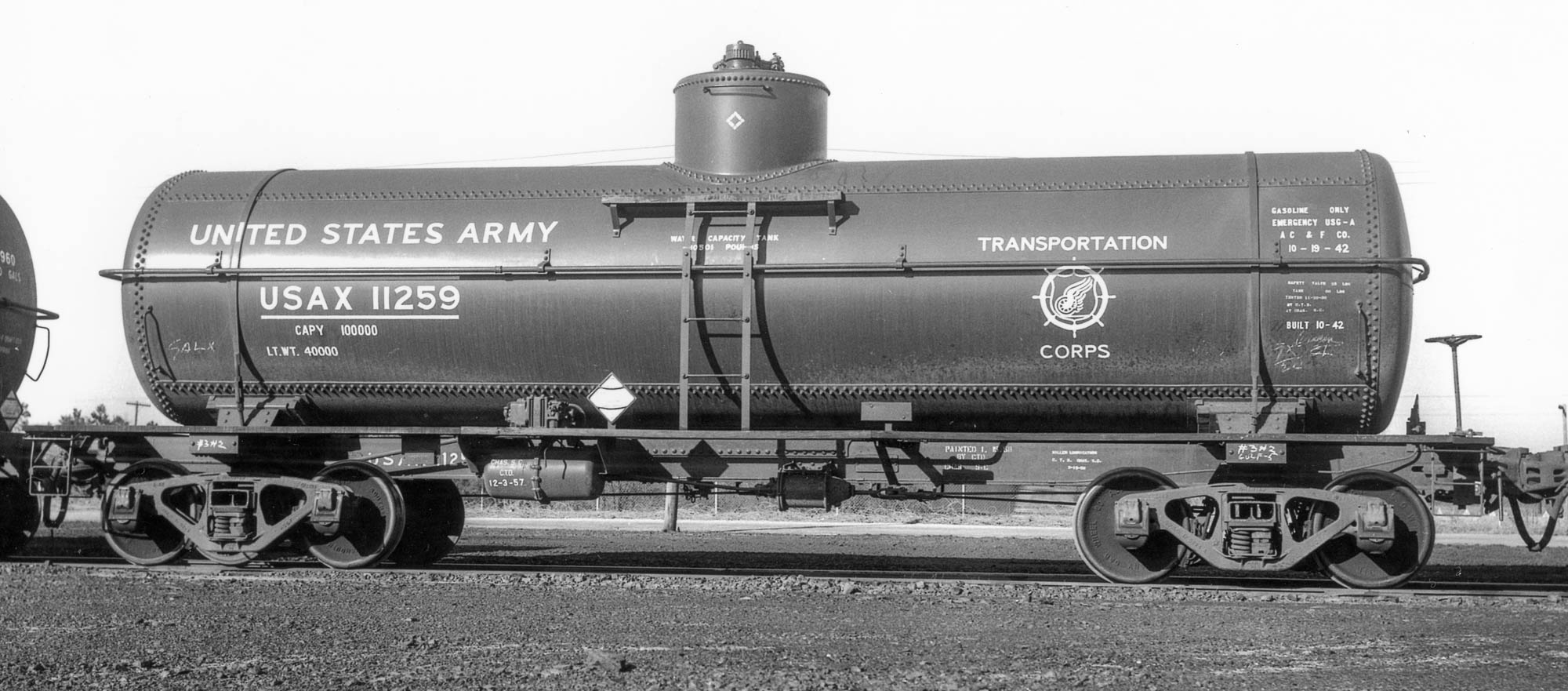
USAX (ex-US Quartermaster's) USG-A 'Emergency' Tank Cars - Part 2

Ft. Bragg, NC, March 27, 1959, Col. Chet McCoid photo, Bob's Photo

In the first post about the USAX (ex-US Quartermaster's) USG-A 'Emergency' Tank Cars, I touched upon the prototype and the first steps in using the Tichy tank car kit to replicate them in HO scale. Here is an update on my progress.

Unlike the SHPX USG-A Emergency cars, these cars built for the US Quartermaster had welded center sills, similar to an AAR underframe, with two zee sections welded along an adjacent edge. The tank anchor was riveted directly to the "face" of the center sill sections. See the detailed photo for reference. Now, I could lie and say that I figured this all out right from the start... but that's not the case. At first, I assumed that there was a cutout in the top cover plate of the center sill to accommodate the tank anchor. Closer examination of this image and the ones in the Mainline Modeler article (Thornton Waite, January, 2006) revealed otherwise. Also, AAR underframes don't generally have top cover plates. So I reacted midstream.


What follows is a mostly blow-by-blow of my steps, including several errors! I removed the part of what are essentially "rests" from the bottom of the tank. These are shown in red in the photo above. I have included the after view, as well. Neatness isn't paramount as these are well-hidden by the tank. 
Before, bottom and after, top

I also modified the tank saddles by filing them to create a more sloped outward facing surface where I will add styrene to connect to the body bolsters. That even included removing part of the outermost wood block on each side of the saddle. However, only a very keen observer will notice that on the finished model. See photo


The tank also had sheet reinforcements at the saddles that were welded to the bottom tank sheet (see prototype closeup at the top of the series of photos above.) I replicated these with 0.005" styrene, 0.40" wide and sized to run essentially from one side of the tank to the other, between the saddles. Lightly bend these pieces of styrene to create a "curl" that matches the bottom tank sheet (I didn't and wish I had; profit from my error!) I taped the center sill/end sill to the tank at the location it would be when finally secured. I then carefully slid the 0.005" styrene between the bottom of the tank and the saddles and moved one into the "perfect" position before carefully tacking it in place with liquid styrene cement (make sure to only tack in place and don't glue the saddles in place; just glue these sheet reinforcements in place.) After the first is tacked in place, repeat the process for the second. Let these set for a little bit (~15 minutes) and then remove the center sill/end sill and apply more liquid cement to secure the styrene and ensure it follows the contours of the bottom tank shell. Note: the rectangular piece in the center of the tank in the photo directly above is/was part of the anchor/center sill cover plate in the kit. It was not used in the model.


I attached the center sill/end sills assembly to the tank, as shown above. First, I glued the saddles to the styrene tank reinforcements. Next, I wanted to add something between the top of the center sill and the bottom of the tank, knowing it would be hidden by the actual anchors once they are added. The purpose is two-fold: add another point where the tank is attached to the underframe and maintain the spacing between the tank and the center sills. I chose to use strip styrene and through trial and error arrived at a piece of styrene 0.045" x 0.080" created from 0.080" strips of 0.015" and 0.030" glued together. Why so precise? If the strip isn't the right size, the center sills will appear to bow or curve up or down (closer or further from the bottom sheet of the tank) which would look highly unrealistic. The strip is highlighted by the yellow arrow in the upper of the two photos directly above. The significance of the red arrows? To highlight my biggest faux pas (so far) on this project. In the upper photo, the red arrows point to the flanges on the top portion of the center sills, which should not be present on a car with zee section center sills. After realizing my error, I carefully removed most of the flanges by scoring and snapping and a little cleanup. Look closely in the lower photo and you will see there are small amounts remaining. These are where the running board supports meet the center sills. I will clean that area up after the supports are added.


Next, I added the tank anchor and center sill flanges. The anchor was fashioned from two pieces of strip created from 0.005" styrene. The one attached to the "face" of the center sills is 10 scale inches wide. The curved cutouts at the end were simulated by using the male portion of a punch and die tapped at an angle, although careful use of a hobby knife could yield similar results. The long portion that abuts the bottom of the tank is seven scale feet long. The upper photo of the two directly above shows the model with the 10-inch strip added. Next, I added a three-inch wide strip, again from 0.005" styrene, abutting the 10-inch strip but attached to the surface of the tank. Note that I angled the corners, common on the flanges attached to the bottom tank sheet. I added 1x6 styrene strips to the center sills to complete the lower legs of the zee sections. Also of note are the areas on the underside of the running boards where I removed strip material. The photo directly above illustrates these details including callouts (the dotted line was added for effect.) That's where the model stands as I type this. More to come in a subsequent installment...

Tuesday, June 7, 2022

Pacific Fruit Express Plywood-sheathed R-30-9


Continuing my effort to push several models into the "finished" camp, I recently completed a PFE plywood-sheathed class R-30-9 refrigerator car. The first part was presented in a clinic (original post and link to files in this post.) The resin parts and decals are offered by National Scale Car.

Finishing the model had a few fits and starts. I elected to finish the car as it would have been painted following its reconditioning at PFE's Los Angeles shops in November, 1949 in the '1948' painting and lettering standard (the only known photo of this car is after it had been repainted in November, 1953 at PFE's Tucson shops.) That car had additional bracing at the body bolsters. I elected to leave those off, but in hindsight, those were likely added in 1949 and not later... my mistake! The main issue in completing the model was the SP Daylight Orange for the sides. I used Scalecoat II Daylight Orange and it proved to be a horrible match, looking rather drab with no orange "punch" to be seen. I repainted the sides with a close approximation created from Tamiya orange, yellow, and touch of red that seems to be a good match. I painted the roof and ends with Scalecoat II Oxide Red and the underframe and trucks with Tamiya Black. There was quite a bit of masking involved!


In preparation for decaling I added a coat of Future floor wax applied with an airbrush. This created a glossy surface conducive to decaling. I applied all the decals, save the repack stencil. I also added a few chalk marks at this time, too. I sealed everything with a coat of Tamiya clear flat. I masked the upper rectangle in the repack stencil blocks (the two blocks at the lower right of the side that have "chevrons" at the left and right edges). I followed that with an application of PanPastels Raw Umber, a good approximation of brownish grime, to all surfaces, trucks included. I removed the masking tape on the repack block and applied another coat of Future followed by a repack stencil on each side as well as numerous chalk marks. I sealed everything again with a coat of clear flat. With the exception of missing paper to simulate route cards, the model is finished.


This has proven to be another extremely satisfying project, from the construction of the side pattern to the completion of the model. For at least the next few weeks (maybe a little more or less) I can rest in the knowledge that I likely have the only completed model of the a PFE plywood-sheathed -9 reefer!

Saturday, October 5, 2019

RPM Chicagoland Chicago Great Western 1937 AAR Box Car Part One

Prototype photo ca. early 1948, Charles Wales, William Hopkins Collection

Naperville, or RPM Chicagoland as it is known now, had been in a bit of a funk for several years. Interest had waned and St. Louis and Cocoa Beach had leapfrogged it as the events to attend on the RPM calendar. One of the things that Mike Skibbe and his dedicated band of volunteers revived was the gift for attendees in the form of a set of parts to kitbash a model into an interesting prototype. They offered a B&O M-15K in 2016. They followed it up in 2017 with a Chicago Great Western 1937 AAR box car that incorporated the distinctive Pullman-Standard Carbuilder’s end.

The entire package included almost everything needed for the kitbash. The attractive Centralia Car Shops box contained a Red Caboose (ex-IMWX) square-corner 1937 AAR box car, resin ends, doors, and details, plus decals (there were corresponding packages for N and O scale modelers.) The instructions were included in the printed and bound meet program, including general arrangement and brake arrangement drawings.

It struck me a little sacrilegious to chop up a perfectly good Red Caboose car. The Intermountain (IM) 1937 AAR cars already come with separate ends, making them suitable models to mate with the resin Carbuilder’s ends. However, when I test fitted the ends to the IM car, I found they were a little too narrow, meaning they did not span the entire width of the car end. I made the decision to cut up the IM car to create a flat kit: sides, ends, roof, and floor/underframe (the prototype underframe had a pair of stringers between the body bolsters and end sills while the IM cars have diagonal supports [see drawing from instructions included at the bottom of this post.] I was willing to overlook this difference if the IM car body was used unmodified. However, since I was creating a flat kit, I opted to use a spare resin floor/underframe.)

Halfway through the car body assembly, illustrating the styrene added at the corners
To create a flat kit from the IM car, I made a series of cuts with a razor saw. The precision of the cuts is less important than avoiding any slips that could damage the side detail. I made vertical cuts to the flat “sub-ends” just inside, finishing all the way into the car body. Once both verticals cuts were complete, I could “flex” the sub-end (still attached at the floor.) Using an Xacto knife, I scored the floor-end joint from the inside of the car body, making several strong passes in both directions. Once scored, it was an easy task to snap away the sub-ends. To remove the sides from the floor, I made two razor saw cuts the length of the car, starting from the bottom of the floor (not from inside the car body,) again with the precision of the cuts not being as important as avoiding damage to the car side detail. I cut all the way through (I did not use the score and snap method because the minimal amount of styrene at the door opening tends to be difficult to get to snap away, leaving one with a side that is missing the portion below the door opening… warning delivered to others, I hope!) Once these two cuts were complete, I removed the excess material from the back of the car sides, leaving two clean and flat car sides.

The sides and ends assembled into the basic car body
At this point, I had two sides, two ends, a roof, and a floor/underframe, ready for assembly. The sides have a relatively thin profile; I wanted a little more surface area for the side-to-end joints. I remedied this by adding 0.125" x 0.125" styrene strip to the back of the sides at the corners, flush with the edges of the sides (leaving some room for the floor and roof parts to be added into the car body.) This provided some extra surface area for a stronger as well as more pronounced 90° joint. I carefully assembled the sides and ends into the basic car body, taking care to ensure that everything was aligned properly and square. Since the joints were resin to styrene, I used ACC. I added extra ACC to the interior to secure these joints. Next I added the floor/underframe casting into the car body. Fortunately, it required almost no filing to fit. I tacked it in place in several spots with ACC and then flowed ACC into the joints from the inside of the car body by adding several drops of ACC and tilting the car body to let the ACC run along the joint until all four joints were filled. I checked the fit of the roof, which required a little amount of filing and added it into the car body, but did not glue it in place at that time. I am still contemplating whether to paint the roof separately as it is black. I also added weight attached to the top of the floor.

The crossbearers as described in the text
The underframe ready for detailing
While I had the floor/underframe casting, I had to scrounge for the associated structural details. I removed the portions of the stringers where the crossbearers are located. I added strips of 0.005" styrene eight scale inches in width to simulate the crossbearer top plates. I fabricated the main crossbearers from 0.010" x 0.100" strips trimmed at an angle to represent the slope of the crossbearers. These were framed by HO scale 1x4 strips on edge. I pre-drilled two for the train pipe, as shown in the photo. I added these to the floor followed by crossbearer bottom plates, again represented by strips of 0.005" styrene eight scale inches in width, but tapered to four scale inches wide at the side sill supports. The crossties are resin pieces from the spare parts bin. The train pipe is represented by 0.020" wire (my holes were not located perfectly, so it is not straight, but from the side, that will not be discernible.) At this point, I was ready to move on to the detailing of the car. That will be covered in Part Two...


A slightly different view of the underframe
This underframe drawing, included in the instructions, illustrates the brake arrangement