Tuesday, August 23, 2022

Texas & New Orleans Emergency Design Gondolas


Merrilees Collection, National Archives of Canada, Neg. no. PA204100

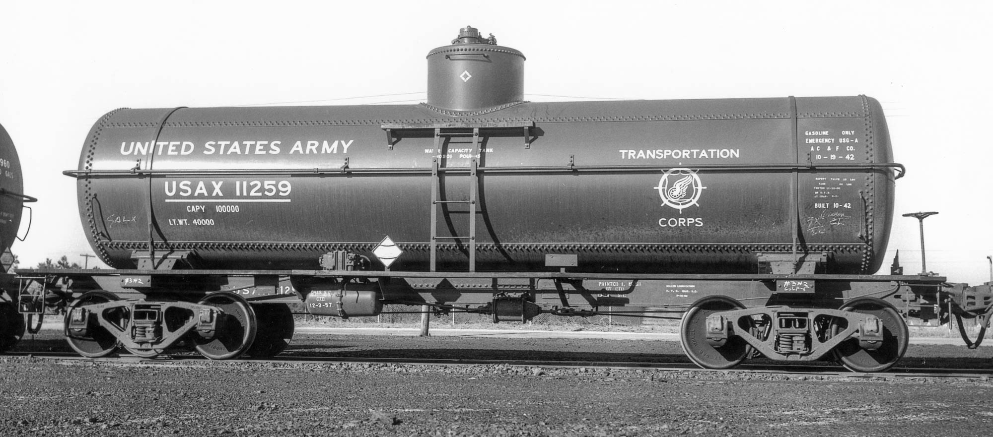
From 1944 to 1951, the Texas & New Orleans added 3,100 gondolas that were based upon the Emergency de- sign 50-ton gondola, substituting wood in place of steel to conserve precious plate steel during the war. However, the T&NO continued to purchase gons that were of composite design even after the restrictions on plate steel were lifted. The cars were assigned to four classes. The data is presented in the accompanying table. 

In 1959, the T&NO began to replace the wood sheathing with plate steel. About half of the cars were converted. When so modified, the class number was amended to include an ‘A’ after the original class number, e.g. G-50-19 became G-50-19-A.

For more information, consult Southern Pacific Freight Cars, Volume 1: Gondolas and Stock Cars, by Anthony W. Thompson, Signature Press, 2002.

Bob's Photo

Jim Gerstley

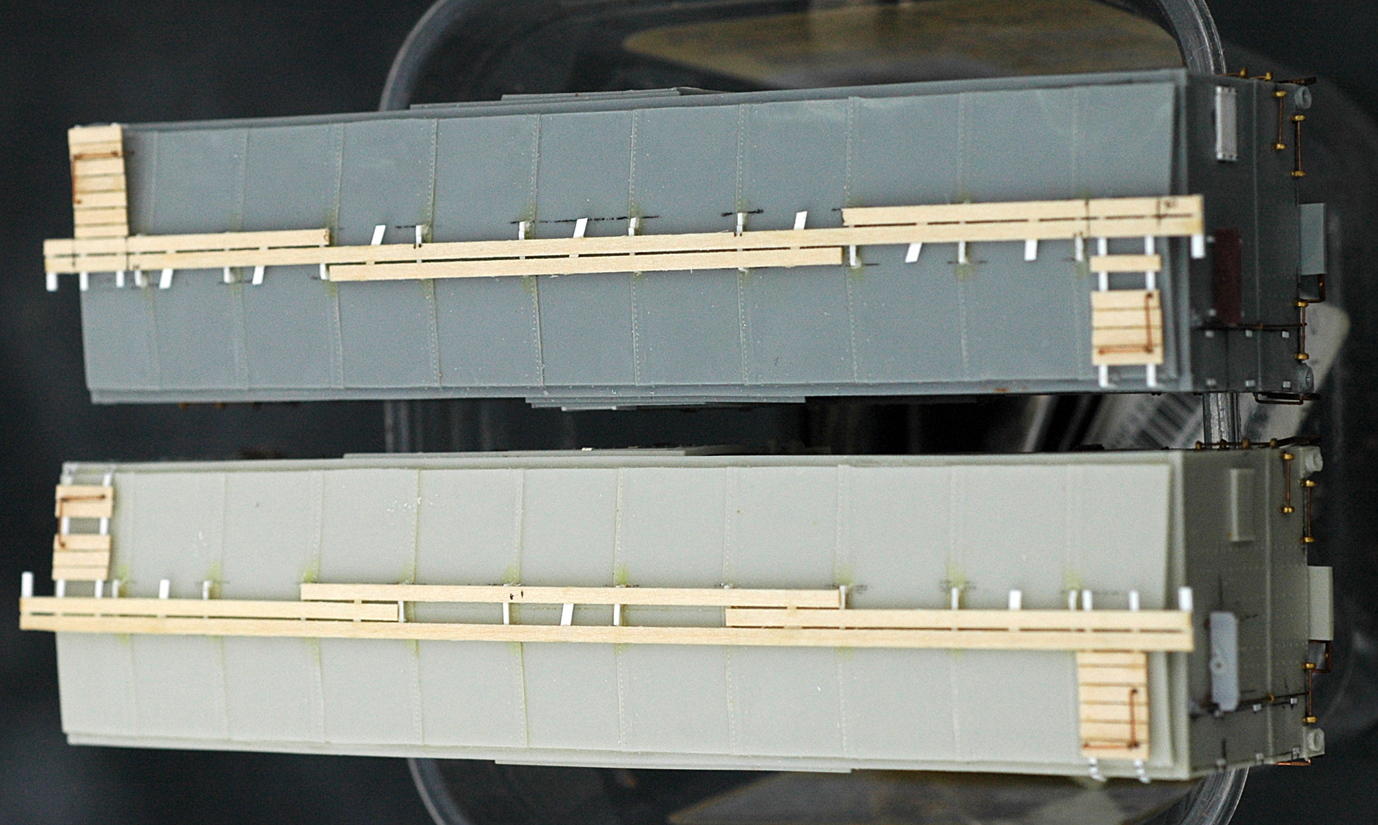
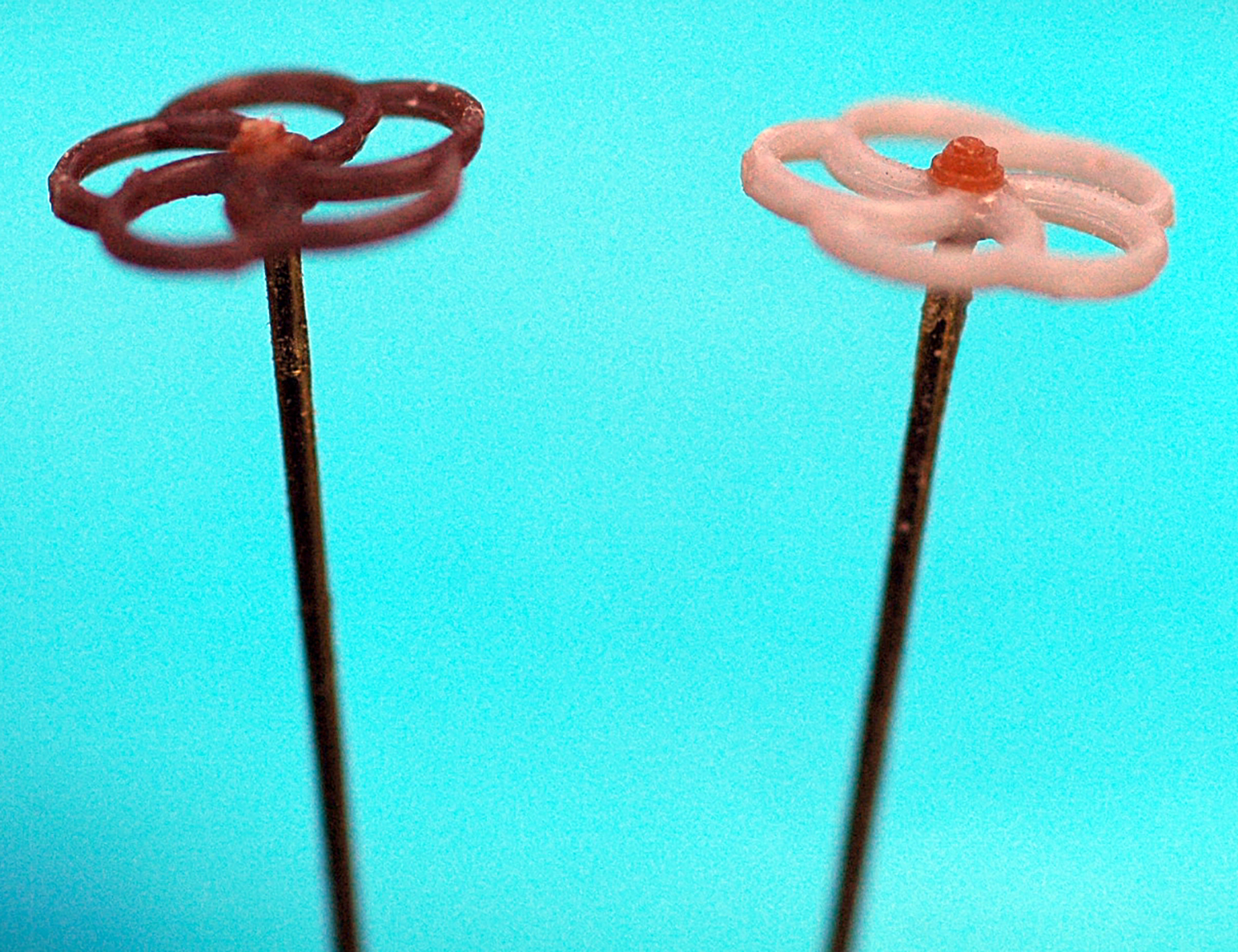
Why am I presenting this information, beyond its prototype importance? As an SP modeler, I am a T&NO modeler to a certain degree, as well. This is a ubiquitous gon, T&NO or not and Funaro & Camerlengo has produced a nice resin kit for the Emergency gon. Therefore, it's a good fit for me. That said, I intend to modify the kit to accept Detail Associates ends, which are an appropriate end for many of the prototypes, plus use the Scullin L-V trucks from Plate C that were used on T&NO nos. 46300-46549 (250 cars, G-50-21) and 48000-48499 (500 cars, G-50-24) and the National Scale Car decals. The next post will begin chronicling the build. Stay tuned

Friday, August 12, 2022

Plate C Model Prototypes HO Scale Trucks


Plate C Model Prototypes has released several HO scale trucks in an expanding lineup. There are some trucks that are of great use to more "modern" modelers from the 60s forward, but there are a few key additions that are useful to Steam/Transition era modelers. Granted, none of those profiled here achieved widespread adoption, but all are unusual in their appearances, with distinctive details that render substitutes nakedly lacking. The first (shown above in model format and below on a prototype) is the Symington-Gould Chrysler FR-5 that I profiled in an earlier post. As I noted in that post, there have been a few avenues for these in HO, but they all pale compared to this new offering. The detail is excellent and they ship with 0.088" semi-scale width treads. I have a GAEX 'DF' box car kitbash on the workbench that will use these.

Hutchinson, Kansas, November, 1951, Harold Vollrath Collection


The second truck that I purchased is the Scullin L-V. These also saw quite limited adoption. I have found a small number of instances of their usage, with two examples  shown here, as well as an ad from the 1953 Car Builders' Cyclopedia. Fruit Growers Express had a few groups of cars that I know were equipped with these trucks. The most notable series is the 39200-39299 series of 14-panel welded cars built at the Indiana Harbor Belt shops in 1949 and the 39300-39499 series, built in the same year. Other examples I have found are the New Haven's 17200-series flats that were converted to TOFC service (the cars not so converted retained their 70-ton trucks,) Pacific Fruit Express R-40-24 nos. 66020-66029 (a very small group of a large series overall,) Norfolk & Western dynamometer car 514780 and Nickel Plate box cars 7010 and 7042 (these were retrofits and the entire series of these cars did not receive Scullin L-V trucks.) One other potentially significant use of these trucks is PFE R-40-23 nos. 7001-7150 and 47703-48202 that specify Scullin bolsters and sideframes, although I do not have photos of cars in these groups to verify that they are Scullin L-V trucks.I plan to replicate one of the 14-panel welded side FGEX cars, so this truck is again a welcome offering.

P.S. in my Steam Freight Car Reference Manual, Volume Three, I erroneously passed on bad information citing these as Chrysler trucks, not doing my own due diligence. I am aware of one other piece of bad information in that work and will post the corrections to the Speedwitch site, as well as on this blog.


Hamlet, NC, April 5, 1959, Col. Chet McCoid photo, Bob's Photo, courtesy of Bill Welch

Bob's Photo


The last truck I will profile here is the Taylor Flexible truck. These also saw limited adoption, but were heavily used by the Reading (unsurprisingly, these trucks were produced in Reading, Pennsylvania; proximity likely played a role in their adoption.)

Fayetteville, North Carolina, December 2, 1951, Col. Chet McCoid photo, Bob's Photo

A couple additional notes are in order. The sideframes/bolsters are 3D printed. As such, their wear over time will be different than the typical engineering plastic trucks we use on most of our cars. If you plan to put these on a car that you run frequently, you are advised to monitor their performance and use a suitable lube to enhance performance and prolong the effective lifespan. Also, the detail on these trucks in better than what is illustrated by my iPhone photos. While not as sharp as a finely-tooled truck, these are quite close and are a far, far better (by orders of magnitude) improvement from the solutions like Cape Line or Eastern Car Works, either in appearance/fidelity or operating characteristics (or both).

Thanks to Dan Smith for pointing out these trucks. I have purchased Plate C's fine hand brakes, but had not visited their site in a while. That will not happen again!

Sunday, July 31, 2022

Sunshine Models X28A/X29 Detailing with Bill Welch


When converted from auto cars, many of the X28A class cars received spliced doors as illustrated here. Bill used the kit door with a strip of 0.005" styrene and rivets to simulate the splice

Over the years, Bill and I had been working on several blog posts demonstrating some of his modeling efforts. Unfortunately, many of them will remain as unfinished projects due to the loss of Bill almost two years ago. It seems fitting to share as many of them as I can present, even in an unfinished state, as Bill's detailing was really the heart of his modeling efforts. What follows are some of the things he did to dress up Sunshine Models kits of the X28A and X29. The captions try to explain the images, which, as was usual with Bill's work, speak for themselves.

This is the "stock" Sunshine X29 with many of Bill's upgrades including a scratchbuilt placard on the door

Bill frequently used wood strips for cars that had wood running boards. He would add many, to be painted the same color as the roof, and leave off a couple to be "unpainted" boards added as repairs. The "missing" boards here would be added after painting.

The corner grab irons on the roof had a long leg and corresponding hole in the roof, to be used to "pin" the latitudinal running boards in place

This image shows the lower left corner of the side of the X28A. Details include Tichy rivets at the body bolster, a Red Caboose route card board (from an X29 kit), brass cast bracket grabs (using the Red Caboose X29 parts as masters) and Yarmouth Scale Models sill steps pinned with brass

Here is the lower right portion of the X28A, including Red Caboose door stops and styrene mounting pads for the ladders

This is a closeup of the lower left of the side of the X29. The details are similar to the X28A shown above

The lower right of the X29

This image shows the B end of both the X28A, at left, and X29. Note the difference. in height.

This is a closeup of the brake step and pressure retaining valve on the X28A

Bill used Red Caboose ladders, but replaced the rungs with 0.010" styrene rod

Bill added Red Caboose hand wheels with Tichy nut-bolt-washers (NBW) at the top


Saturday, July 23, 2022

USAX (ex-US Quartermaster's) USG-A 'Emergency' Tank Cars - Part 2

Ft. Bragg, NC, March 27, 1959, Col. Chet McCoid photo, Bob's Photo

In the first post about the USAX (ex-US Quartermaster's) USG-A 'Emergency' Tank Cars, I touched upon the prototype and the first steps in using the Tichy tank car kit to replicate them in HO scale. Here is an update on my progress.

Unlike the SHPX USG-A Emergency cars, these cars built for the US Quartermaster had welded center sills, similar to an AAR underframe, with two zee sections welded along an adjacent edge. The tank anchor was riveted directly to the "face" of the center sill sections. See the detailed photo for reference. Now, I could lie and say that I figured this all out right from the start... but that's not the case. At first, I assumed that there was a cutout in the top cover plate of the center sill to accommodate the tank anchor. Closer examination of this image and the ones in the Mainline Modeler article (Thornton Waite, January, 2006) revealed otherwise. Also, AAR underframes don't generally have top cover plates. So I reacted midstream.


What follows is a mostly blow-by-blow of my steps, including several errors! I removed the part of what are essentially "rests" from the bottom of the tank. These are shown in red in the photo above. I have included the after view, as well. Neatness isn't paramount as these are well-hidden by the tank. 
Before, bottom and after, top

I also modified the tank saddles by filing them to create a more sloped outward facing surface where I will add styrene to connect to the body bolsters. That even included removing part of the outermost wood block on each side of the saddle. However, only a very keen observer will notice that on the finished model. See photo


The tank also had sheet reinforcements at the saddles that were welded to the bottom tank sheet (see prototype closeup at the top of the series of photos above.) I replicated these with 0.005" styrene, 0.40" wide and sized to run essentially from one side of the tank to the other, between the saddles. Lightly bend these pieces of styrene to create a "curl" that matches the bottom tank sheet (I didn't and wish I had; profit from my error!) I taped the center sill/end sill to the tank at the location it would be when finally secured. I then carefully slid the 0.005" styrene between the bottom of the tank and the saddles and moved one into the "perfect" position before carefully tacking it in place with liquid styrene cement (make sure to only tack in place and don't glue the saddles in place; just glue these sheet reinforcements in place.) After the first is tacked in place, repeat the process for the second. Let these set for a little bit (~15 minutes) and then remove the center sill/end sill and apply more liquid cement to secure the styrene and ensure it follows the contours of the bottom tank shell. Note: the rectangular piece in the center of the tank in the photo directly above is/was part of the anchor/center sill cover plate in the kit. It was not used in the model.


I attached the center sill/end sills assembly to the tank, as shown above. First, I glued the saddles to the styrene tank reinforcements. Next, I wanted to add something between the top of the center sill and the bottom of the tank, knowing it would be hidden by the actual anchors once they are added. The purpose is two-fold: add another point where the tank is attached to the underframe and maintain the spacing between the tank and the center sills. I chose to use strip styrene and through trial and error arrived at a piece of styrene 0.045" x 0.080" created from 0.080" strips of 0.015" and 0.030" glued together. Why so precise? If the strip isn't the right size, the center sills will appear to bow or curve up or down (closer or further from the bottom sheet of the tank) which would look highly unrealistic. The strip is highlighted by the yellow arrow in the upper of the two photos directly above. The significance of the red arrows? To highlight my biggest faux pas (so far) on this project. In the upper photo, the red arrows point to the flanges on the top portion of the center sills, which should not be present on a car with zee section center sills. After realizing my error, I carefully removed most of the flanges by scoring and snapping and a little cleanup. Look closely in the lower photo and you will see there are small amounts remaining. These are where the running board supports meet the center sills. I will clean that area up after the supports are added.


Next, I added the tank anchor and center sill flanges. The anchor was fashioned from two pieces of strip created from 0.005" styrene. The one attached to the "face" of the center sills is 10 scale inches wide. The curved cutouts at the end were simulated by using the male portion of a punch and die tapped at an angle, although careful use of a hobby knife could yield similar results. The long portion that abuts the bottom of the tank is seven scale feet long. The upper photo of the two directly above shows the model with the 10-inch strip added. Next, I added a three-inch wide strip, again from 0.005" styrene, abutting the 10-inch strip but attached to the surface of the tank. Note that I angled the corners, common on the flanges attached to the bottom tank sheet. I added 1x6 styrene strips to the center sills to complete the lower legs of the zee sections. Also of note are the areas on the underside of the running boards where I removed strip material. The photo directly above illustrates these details including callouts (the dotted line was added for effect.) That's where the model stands as I type this. More to come in a subsequent installment...