Showing posts with label USAX. Show all posts

Saturday, July 23, 2022

USAX (ex-US Quartermaster's) USG-A 'Emergency' Tank Cars - Part 2

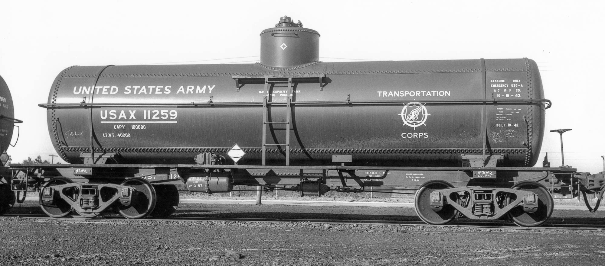
Ft. Bragg, NC, March 27, 1959, Col. Chet McCoid photo, Bob's Photo

In the first post about the USAX (ex-US Quartermaster's) USG-A 'Emergency' Tank Cars, I touched upon the prototype and the first steps in using the Tichy tank car kit to replicate them in HO scale. Here is an update on my progress.

Unlike the SHPX USG-A Emergency cars, these cars built for the US Quartermaster had welded center sills, similar to an AAR underframe, with two zee sections welded along an adjacent edge. The tank anchor was riveted directly to the "face" of the center sill sections. See the detailed photo for reference. Now, I could lie and say that I figured this all out right from the start... but that's not the case. At first, I assumed that there was a cutout in the top cover plate of the center sill to accommodate the tank anchor. Closer examination of this image and the ones in the Mainline Modeler article (Thornton Waite, January, 2006) revealed otherwise. Also, AAR underframes don't generally have top cover plates. So I reacted midstream.


What follows is a mostly blow-by-blow of my steps, including several errors! I removed the part of what are essentially "rests" from the bottom of the tank. These are shown in red in the photo above. I have included the after view, as well. Neatness isn't paramount as these are well-hidden by the tank. 
Before, bottom and after, top

I also modified the tank saddles by filing them to create a more sloped outward facing surface where I will add styrene to connect to the body bolsters. That even included removing part of the outermost wood block on each side of the saddle. However, only a very keen observer will notice that on the finished model. See photo


The tank also had sheet reinforcements at the saddles that were welded to the bottom tank sheet (see prototype closeup at the top of the series of photos above.) I replicated these with 0.005" styrene, 0.40" wide and sized to run essentially from one side of the tank to the other, between the saddles. Lightly bend these pieces of styrene to create a "curl" that matches the bottom tank sheet (I didn't and wish I had; profit from my error!) I taped the center sill/end sill to the tank at the location it would be when finally secured. I then carefully slid the 0.005" styrene between the bottom of the tank and the saddles and moved one into the "perfect" position before carefully tacking it in place with liquid styrene cement (make sure to only tack in place and don't glue the saddles in place; just glue these sheet reinforcements in place.) After the first is tacked in place, repeat the process for the second. Let these set for a little bit (~15 minutes) and then remove the center sill/end sill and apply more liquid cement to secure the styrene and ensure it follows the contours of the bottom tank shell. Note: the rectangular piece in the center of the tank in the photo directly above is/was part of the anchor/center sill cover plate in the kit. It was not used in the model.


I attached the center sill/end sills assembly to the tank, as shown above. First, I glued the saddles to the styrene tank reinforcements. Next, I wanted to add something between the top of the center sill and the bottom of the tank, knowing it would be hidden by the actual anchors once they are added. The purpose is two-fold: add another point where the tank is attached to the underframe and maintain the spacing between the tank and the center sills. I chose to use strip styrene and through trial and error arrived at a piece of styrene 0.045" x 0.080" created from 0.080" strips of 0.015" and 0.030" glued together. Why so precise? If the strip isn't the right size, the center sills will appear to bow or curve up or down (closer or further from the bottom sheet of the tank) which would look highly unrealistic. The strip is highlighted by the yellow arrow in the upper of the two photos directly above. The significance of the red arrows? To highlight my biggest faux pas (so far) on this project. In the upper photo, the red arrows point to the flanges on the top portion of the center sills, which should not be present on a car with zee section center sills. After realizing my error, I carefully removed most of the flanges by scoring and snapping and a little cleanup. Look closely in the lower photo and you will see there are small amounts remaining. These are where the running board supports meet the center sills. I will clean that area up after the supports are added.


Next, I added the tank anchor and center sill flanges. The anchor was fashioned from two pieces of strip created from 0.005" styrene. The one attached to the "face" of the center sills is 10 scale inches wide. The curved cutouts at the end were simulated by using the male portion of a punch and die tapped at an angle, although careful use of a hobby knife could yield similar results. The long portion that abuts the bottom of the tank is seven scale feet long. The upper photo of the two directly above shows the model with the 10-inch strip added. Next, I added a three-inch wide strip, again from 0.005" styrene, abutting the 10-inch strip but attached to the surface of the tank. Note that I angled the corners, common on the flanges attached to the bottom tank sheet. I added 1x6 styrene strips to the center sills to complete the lower legs of the zee sections. Also of note are the areas on the underside of the running boards where I removed strip material. The photo directly above illustrates these details including callouts (the dotted line was added for effect.) That's where the model stands as I type this. More to come in a subsequent installment...

Tuesday, May 3, 2022

USAX (ex-US Quartermaster's) USG-A 'Emergency' Tank Cars


In 1942-3, American Car & Foundry built Emergency-design, designation USG-A tank cars for SHPX leasing services as well as for the US War Department, Office of the Chief of Transportation (US Quartermaster) under USQX reporting marks, series 11168-11178, 11200-11309, and 11311-11475 (four cars in 11168-11178 had two domes/two compartments). The cars used contemporary underframes with World War One era tank designs. The late Richard Hendrickson authored an article about the cars in the October, 1990, RailModel Journal, available online via this link.

Modelers are fortunate to have excellent HO scale versions of the tanks from Tichy (originally Gould.) Many (if not all) of the SHPX tanks were scrapped/recycled in the postwar era, with the underframes being re-used, but the USQX cars soldiered on under USAX reporting marks (there were also Canadian prototypes, profiled by Russ Pinchbeck, including modeling, in the July, 2002, Railroad Model Craftsman.) There was also an article about the USAX cars by Thornton Waite in the January, 2006, Mainline Modeler. That is the inspiration for this project.

I have a seemingly great number of freight car projects nearing completion, so in between those painting, decaling, and weathering duties, I have dabbled a little in this project. I started with a Tichy tank car kit with a 54-inch dome width. There are several modifications to arrive at a USAX prototype, including modification of:

  • the location of the safety valves (I added other details, too)
  • the tank anchor
  • the tank bolsters
  • the underframe


Thus far, I have made changes to the dome. The overlap of the tank shell on the dome is quite simple, to the point that it seems to be almost missing. I removed the rivets and added a strip of 0.005 thousand styrene, blending it into the face of the dome at left, and leaving a sharp edge at right, as shown in the photo directly above. I will (re)apply rivets to the dome in the appropriate locations.


I also removed the safety valve locations, reserving the "center" of the valve locations. I puttied and sanded the old locations and then added discs to the top of the dome for the new locations, as shown. I then added the valve "centers" that had been salvaged, being careful to orient them so the top was "level" as these had gently sloped (actually curved) bottoms so that the top would be level. Somewhere in all of this, I added the dome to the tank and secured it with solvent cement.


Next up in this series: the tank anchors and body bolsters. I have been working on artwork for USAX/US Army Transportation Corps lettering...