Showing posts with label Tools. Show all posts

Friday, May 17, 2024

A simple, effective tool


There are times when one needs to sand a surface that is not easily accessible by our pudgy digits, even if using something as ingenious as Tight Spot Sanders. I recently had need to do a little sanding in just such an area. Years ago, I had made (and misplaced) a functional little sanding tool. I decided to (re)make one. It's a simple thing. I used 0.125" styrene rod, sawed at an angle using a razor saw, a piece of 0.040" x 0.100" strip (0.040" x 0.125" would be more logical, but I am out of that size,) two-part epoxy, and sandpaper. Glue the strip to the angled face of the rod, let dry, then attach sandpaper to the bottom of the strip using two-part epoxy, let dry again, trim the edges of the sandpaper, and you're ready to use. You could make several using different grades/grits of sandpaper.


Saturday, May 6, 2023

A little tool time


I recently decided to attempt to find a better alternative for cleaning my airbrush. After some simple searching, I found the Torrington Brush Works web site. I ordered nylon micro-tube brushes in several sizes, from 0.020" brush diameter through 0.080" brush diameter in 0.010" increments. I can report that they are exactly what I was seeking. The larger ones can pass through the entire length of my airbrush and the smallest can pass through the tip of the airbrush (be careful as. the opening in the tip can be easily split, even though it is metal.) If you're looking for brushes, I recommend a visit to the Torrington Brush Works site. 

Editorial content: Yes, I am certain you can find a better deal on amazon. However, my preference is to support a small business. Your mileage may vary

the "business" ends of the 0.050" and 0.060" diameter brushes


Wednesday, March 8, 2023

Larger Etching Bending Tool - RP Toolz Piranha

In my presentation about etchings, I mentioned that I was in the market for an etching bending tool with a longer bending edge. In the past, I have used a small "Hold and Fold" from the Small Shop. I first visited their site looking for a larger version of their tool, but found that it has been discontinued. My next stop was UMM-USA where I found just the thing, the RP Toolz "Piranha" 195mm photo etch bending tool. I ordered it ($60.99) and it arrived within a few days. Not only do I love its longer working edge, but I have also found it to have stronger clamping than the Hold and Fold, making it easier to bend some of my recent creations that have long edges, but relatively narrow bits to grab to facilitate bending. The top piece can be unscrewed and rotated 180 degrees, as well, providing some flexibility. I am 100% satisfied with the Piranha. I highly recommend it. If this is too large for your needs, UMM-USA does have other options. Just use the search tool at their site.

In the next couple days, I will share a few updates to etched parts I referenced during the presentation

Wednesday, October 7, 2020

More Tools


Blade One Nipper Item Code: GODGH-PN-120 

I frequently espouse keeping up with the goings-on within the military modeling community. They seem to operate in a parallel world that sometimes intersects with ours, but seemingly should more often. Over the years, I have found many incredibly useful tools that those guys use that we in the model railroading community know little about. These tools from GodHand are good illustrations. The nippers are incredible. Their cutting edge is quite sharp and the leverage of the cut is solid, with the cutters doing the work. The sharpness of the cutting edges means that things that would often deform through cutting, such as hollow tubelike shapes, do not; the cutting action starts before any "crushing" forces are imparted, making them extremely delicate. They won't make my Swiss nippers obsolete, as their jaws are not as fine, but they have firmly established a place in the tool box.


The other find from GodHand are these chiseling tips. Think of them as the old Xacto no. 17 blade on many doses of steroids. They are incredibly sharp (as in be very careful sharp.) They are also substantial hardened metal, making them work with less effort than the old Xacto blade. There is far less "slippage" since these do their work with less effort. I have used them many times and love them; I can't wait to try them to remove the end detail from an MDC 50' single sheathed auto car. The handle shown above is an Excel handle from MicroMark (Excel part no. 30605.) I purchased the GodHand items from HobbyLink Japan, but you can find them on eBay, too. Postage was modest and they arrived quickly.

Left item (green) is Bit Blade: Flat Blade Set of 5pcs Item Code: GODGH-BBH-1-3
Right item (red) is Bit Blade: Round Blade Set of 5pcs Item Code: GODGH-BBM-1-3


Thursday, July 30, 2020

Simple Tool


This is a very short post from vacationland up in the Adirondacks. Anyone who has worked in an office for the last decade has likely seen these things, although you may not have paid them much attention. They are the skewers used for fruit in the fruit "bouquets" marketed by Edible Arrangements. As a modeler always looking at the functionality of things, I thought they might be useful and grabbed a bunch. They proved be quite useful for two things. One end is shaped akin to a Phillips head screwdriver. That one functions well as a manual uncoupling tool. The other end works as a handle for holding truck sideframes while painting. Simply slide the bolster truck mounting hole over the tool. It is a particularly good fit for Tahoe Model Works truck sideframes.

Sunday, February 3, 2019

Mission Models Chisel Tool


In my recent kitbashing clinic at Prototype Rails, I (again) left out description of a specific tool that I use frequently and love (too strong a word?) The tool is the Mission Models chisel. I have omitted it from clinic discussions because I erroneously thought that it or similar proxies were not available (I purchased mine directly from Mission Models over a decade ago; Mission is now defunct, although there is an unrelated Mission Models website that sells paint and modeling supplies.) On a whim, I searched google and discovered that not only is the Mission Models tool still available from Sprue Brothers, as well as on ebay, but UMM-USA also now markets a similar product (Ultra Micro chisels) in multiple size blades. These sites both cater to the military modeling community.


What is the value of this tool? If you frequently use an Xacto no. 17 chisel blade, the Mission Models and UMM-USA chisels are not necessarily direct replacements. Their advantages are a few. First, the cutting blade is far narrower than a no. 17 chisel, making it more precise and able to fit into tighter areas, where a larger wayward no. 17 blade could mar detail that one wants left untouched. Additionally, because the blade is created from hardened steel with a shorter rounded base, it is far stronger than a no. 17 chisel (I have had no. 17 blades snap in half; that will not happen with a Mission Models chisel blade.)


As noted above, there are a few different blades available. For the Mission Models versions, the blades may be interchanged in the handle and tightened using a set screw. The UMM-USA versions have integral handles that are similar to the Mission Models. However, rather than swapping out the chisels, you simply buy each chisel/handle separately.

Tuesday, March 8, 2016

Frogtape


That familiar harvest yellow reminds you of another brand, huh?
Many of us have come to love using Tamiya's masking tape. When used for masking paint, it creates crisp edges yet it doesn't pull up paint like many other masking tapes. It has a well-deserved reputation among modelers for getting the job done. Unfortunately, like many specialty items that we use, particularly those from Tamiya, its price carries a premium compared to the diminutive size of the rolls.


There is an excellent alternative that costs a fraction of what Tamiya does and performs just as effectively. Frankly, I think it is the same stuff. I found mine at a Sherwin-Williams paint shop, but I am sure it can be purchased elsewhere. It's called Frogtape and is marketed to interior house painters as, you guessed it, a superior masking tape that doesn't pull up the paint underneath it. I have rolls that are 24mm (0.94 in) and 36mm (1.41 in) wide, both in 60 yard lengths. That might be a lifetime supply for modeling. I highly recommend it.

Friday, March 4, 2016

Starrett Tools

One of the things that can be either maddeningly frustrating or joyously satisfying is doing something that requires a tool. Cheap knockoffs of hand tools that are manufactured in Pakistan and sold at train shows for about 1/20th the price of their American, Swiss, Japanese, German, etc., counterparts are good cases in point. Yes, they are bargains, but sometimes you get exactly the price you pay. I generally steer clear of these items as the lack of quality makes their use frustrating, unless I know that it is a tool where quality is not the primary consideration.

When I am measuring or cutting and precision of the edges is paramount, I thank my lucky stars that I have these small Starrett squares. Yes, they are more expensive than most comparable items. However, they are machinist's quality and I know that the edges are straight and they line up exactly perpendicular to the edge against which they rest. It's as simple as that. No more explanation needed.

Another Starett tool that I own is the pin vise pictured here. I don't know the model number, but I believe the current equivalent in their line is the 162A pin vise. Most of us who build and detail model railroad items use small drill bits. I have and use ones that are sub-no. 80, down to about 0.0065". Ever try to put one of these or even a no. 80 bit into one of the hobby shop pin vises or a supposed jeweler's pin vise? You already know what happens. The collet can't close down enough and the bit isn't secure (or it may appear to be secure and then start to disappear into the collet once you start to drill). This pin vise securely holds even the smallest bits that I use. The other great thing is that it is extremely well-balanced and easy to use.

Give Starrett Tools a look. Having the right tool for a job can make it joyously satisfying...

Wednesday, February 24, 2016

Building the Speedwitch Southern gondola

The gon as viewed from the underside with strip added and underbody glued into the car body
The Southern gondola kits were my first efforts when I launched the resin portion of Speedwitch. To say that I tried to have my cake and eat it, too, is an understatement. I hated gondola models where there was a sacrifice in that either the interior side walls weren’t tall enough relative to the prototype or there wasn’t anywhere to conceal some weight. I was determined to make a car where the interior was “the way it should be” and you could still stash some weight. As with most open top scale models, something had to give. In this case, the “give” was the depth of the underframe. I purposely made the bolsters, crossbearers, crossties, and center sills shallower than the prototype in order to achieve a prototypical car interior and have somewhere to put some weight. That also meant that the coupler pockets were forced to sit right on the underside of the gondola floor, in a “cut-out” in the underbody. This also makes it a challenge to secure the coupler pockets. In retrospect, I probably bit off too much. I am certain there are many out there who are still trying to figure out how to build one of these successfully. What follows is what I hope will be a step-by-step guide to augment the kit’s instructions and explain one person’s path to building the car into a beautiful and operable model.
The interior with the floor attached
The initial step is to clean up the main body casting, comprised of sides and ends. My course of action was to rub it back and forth on a sheet of 220-grit sandpaper on a flat surface. I held the casting in between thumb and forefinger and rubbed the casting parallel to the line of the surface I was holding, switching the places I was holding frequently to avoid removing too much material in any one location. By “parallel to the surface I was holding,” that means that if I was holding the car side, I moved the length of the car side back and forth along the sandpaper. Conversely, if holding the end, I moved the length of the end back and forth across the surface of the sandpaper. In a fairly short amount of time, the casting “flash” inside the top of the car body became thin enough to flick away in most places. In those areas where there was still a little material holding the flash in place, I held the casting in that specific area and moved it across the sandpaper as described previously. Once the excess material had been removed, I cleaned up the top edges of the car with a sanding stick (read about sanding sticks by clicking.)
An additional view with the underbody added and the strip styrene visible at the edge
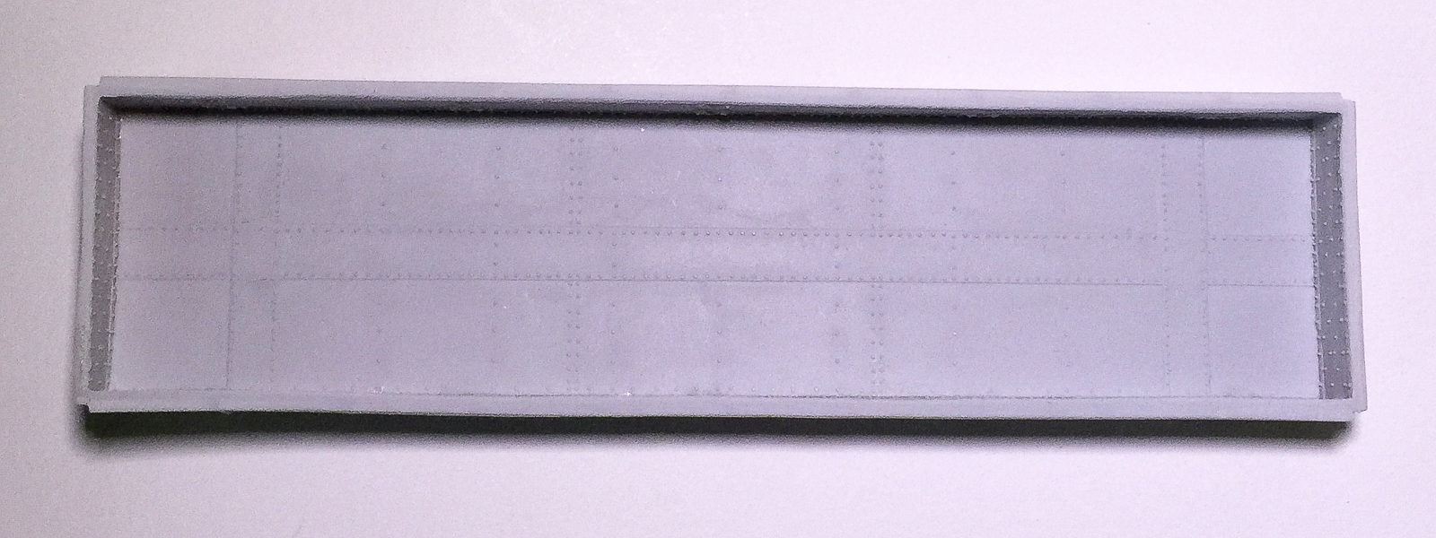
The first snafu involves the floor of the gondola. This is the part with detail on its surface that fits inside the car body and faces up when the car is on the rails. It is slightly too long (this is okay) and slightly too narrow (not okay.) It must be made marginally wider. To do this, I added 0.020” x 0.020” styrene strip to the edges (the long edges) of the casting. This was actually really easy to do. I simply laid the casting on a flat surface with the styrene strip butted against it and held in place by my finger and added a little ACC along the length using a straight pin as an applicator, moving my finger as I went, to expose the areas I hadn’t attached. It took less than five minutes. Work in small drops rather than big gobs and there will be no ACC mess or parts stuck to your work surface. It doesn’t hurt to keep checking as you go, though, to make sure your part isn’t attaching itself to your work surface. With the styrene strip added, the casting is ever so slightly too wide. A few (and I mean a few) passes of the casting over sandpaper on a flat surface should narrow things enough to fit inside the car body. To do this, hold the casting on edge and run it over the sandpaper. I always run it the same number of passes in one direction, the other direction and then flip and do the same for the other side. It’s not entirely scientific, but it does remove roughly the same amount from both sides. Do the same to shorten the ends of the casting and it should fit snugly, but not tightly, inside the car body. It fits inside the lip that is in the car body, meaning the edges of the casting you just narrowed will not be visible once the floor is glued inside the car body, if viewed looking “into” the car body, as you would if it were on the rails.
From the top, the undeframe, car body and underside of floor, and the lead weight, all with the Goo and MEK mixture added to the surfaces
Gluing the floor inside the car body is a relatively easy process. Put the car body casting on a flat surface upside down, with the top edges of the car body in contact with the flat surface. Place the floor inside the car body. You should be looking at the undetailed (“underside”) surface of the floor. If you are looking at the rivets, stop and reorient the parts. To glue the floor into the car body, there are two key things to consider: 1) work in small increments, rather than trying to glue it all at once and 2) a light pressure is all that is needed; a death grip will surely create distortions in your body casting meaning either the sides will be grossly bowed or you will induce “torque” along the length of the car body, resulting in a pronounced twist to the body. Gently push the floor into the car body so that the floor rests inside and snugly against the lip in the car body. I found it easiest to start at the center of the car and then work towards one end followed by the other. With light pressure, gently press the car body together with thumb and middle finger while applying slight pressure with the index finger to keep the floor pushed into the car body. The thumb and middle finger should be applying pressure near the edge of the car body that is closest to you (and where the floor casting is contacting the car body), not the edge that is touching the flat surface on which you are working. Applying pressure where the car body is resting on the flat surface will cause the car sides to bow, angle or cant inwards. Gentle pressure using this three-point approach with thumb and two fingers applies all the force necessary to keep things in place while you add the ACC. Add some ACC where you are applying the pressure to the joints on both sides of the car body (at the places where both thumb and middle finger are holding things together). Hold until the ACC has set up the joint. Repeat at several points until the floor is secure from the middle to one end and then repeat from the center to the other car end. As you work, make sure that the floor is nested all the way into the lip in the car body. This is your one chance to get this correct. Go slowly, checking your progress frequently. Once you have tacked everything in place, go back and add ACC along the entire floor/car body joint. If all is well, you should have the “bones” of a gondola in your hands!
The car body with weight attached and awaiting addition of the underbody casting
The next series of tasks involve addition of weight between the floor and underbody followed by gluing the underbody into the car body. For the weight, I have a large roll of 0.020” thick sheet lead that is perfect for this car (I believe it is some type of flashing for use in the roofing industry). I cut a piece of lead to fit exactly into the cavity under the floor, minus the notched areas where the coupler boxes would be located. I “painted” the underside of the car floor and the top of the weight with a mixture of Walthers Goo and methyl ethyl ketone (MEK). The MEK makes the Goo less viscous and able to be brushed on to surfaces. Once the Goo had thoroughly dried, I dropped the weight into the cavity and carefully pressed the two surfaces together, between thumb (on the lead surface) and forefinger (inside the car body). Don’t put the car body upside down on your work surface and just push on the underbody. You could damage or deform the car body. Use the thumb-forefinger technique described above as it places pressure only on the floor and underbody, not the car body. I brushed the Goo on to the still exposed lead surface and the “top” of the underbody. Once again, I let the Goo dry before adding the underbody and again pressing the surfaces between thumb and forefinger. This completed the basic assembly of the car body.

The modified coupler boxes as described in the text
The coupler and "draft gear" as attached to the model
The next task was the addition of the couplers. I used Kadee no. 153 scale couplers in the Kadee-supplied coupler boxes (“draft gear”) modified as shown. The no. 153 coupler is the same as the standard no. 158, but with a shorter shank length that was better for this car. The basic modifications included shortening the main half of the coupler box (the piece with the circular post and the “sides” of the coupler box) to butt against the inside of the end sill, and narrowing the front lip of the other half of the coupler box to fit between the draft gear opening of the car body’s end sill. Lastly, I added bits of HO scale 1x4 strip styrene to complete the “sides” of the coupler box that extend past the draft gear. The next challenge to overcome involved actually securing the coupler boxes to the car body. After some deep thought, I came up with the following plan: I would run a piece of 3/32” styrene tube through the post of the coupler box and, after drilling a hole in the floor, straight through the floor of the car. Yes, it meant a piece of styrene rod protruding from the floor of the car and subsequent sanding and cleaning up of the car floor after my “surgery”. The converse, though, is that I had a secure means to attach the couplers, beyond just gluing them (and we all know how that ends up: a coupler and lid sitting somewhere on the layout with half a train sitting uncoupled behind the coupler!) After all, the styrene rod isn’t moving and it has a hole that can accept a screw to secure the coupler boxes. That’s what I did. After everything was in place, I added a small bit of styrene rod into the center of the styrene tube visible on the top of the car floor (the hole in the tube on the underside of the car needed to remain clear to accept a 0-80 screw to secure the coupler box.) I am in the process of filling and sanding the floor of the car to clean up my mess. That’s where I will leave things for the moment. Because the tight spaces on the floor between rows of rivets dictate careful sanding, I created my own sanding tool that is a piece of styrene tube, cut at an angle at one end, with a piece of 4x10 HO scale styrene strip glued to the angled end, with a piece of sandpaper glued to the face of the strip (using the Goo/MEK solution). I had made some of these years ago for a similar situation, and I cannot remember if it is something that I created or saw somewhere else and emulated. Either way, it’s the right tool for the situation. See the photo.
Note the visible styrene rod at each end. As viewed here, all that remains is some fine sanding
The "tool" that I created for sanding the top of the floor. It consists of styrene tube, a bit of strip styrene, and some sandpaper glued to the face of the strip
All the hard work is done and I have proven that my over-engineered gondola can be built, although it takes a little planning and ingenuity. To be continued as the car is detailed and painted…
A view of the underbody

Monday, February 22, 2016

MinuteMan Scale Models Wheel Painting Jig

MinuteMan Scale Model HO scale wheel painting jig
For several years I have used the wheel painting jig offered by American Model Builders. It is a clear acrylic laser cut jig that one glues together. When I purchased it, I appreciated its simplicity and great value. I did have one complaint: the way the jig is arranged, the wheelsets are too close together to easily allow complete painting of the two "interior" wheelsets (the ones not at the edges of the jig). However, given that it otherwise performed its intended function and there was not an alternative, I made do. I ordered this jig from MinuteMan Scale Models a couple months back and it is everything the AMB jig was, but has a greater space between each wheelset, allowing my airbrush access to easily paint the surface of all the wheelsets. Problem solved. It's nice when you can get a product that solves the problem of the product which it replaces!

P.S. MinuteMan is also the new owner of Scalecoat paints, for those of you who prefer Scalecoat

Thursday, February 11, 2016

In praise of sanding sticks

My pile of sanding sticks and pads

In one of my dalliances with aircraft modeling, I started using sanding sticks and pads for some of the cleanup work and filing that is an inherent part of model building. While I am sure that many know about them, there may be a few out there who do not, and I feel their value means that all modelers should be aware of them and use them regularly.

While you can buy them from hobby specialists such as Micro-Mark or Squadron, you can do almost just as well, for less money, at your local drugstore. Look in the nail care section of the store.

Now for the why. You may be asking, "I already have mill files, needle files, and sandpaper. Why do I need more sanding tools?" I'm glad you asked that question. Have you ever been merrily filing something and had that, "Oh, sh.... sugar!" moment? You got a little careless or your mind wandered and you suddenly removed more material than you wanted. While the sanding sticks may not prevent all those "whoops" moments, they do prevent many. The reason is that the sanding surface is backed by a dense padding. It provides just a little "give" to the sanding surface and is less "aggressive" than a file. That translates to a little more softness when sanding and edges that are more nicely dressed or finished. In turn, that means better looking models, which is the goal.

Another benefit is the number of finishes available. There are gradations of texture from quite rough down to the equivalent of polishing-grade and everything in between. It's a range that files can't match. While sandpaper has the same range of grit or textures, sandpaper lacks the padded backing with its inherent flexibility.

What are the drawbacks? Sanding sticks and pads are not generally good at getting into tight areas. For very fine applications where you need precise control to avoid accidentally removing a specific detail, they are at a disadvantage because of their size and/or lack of rigidity, as compared to a needle file. They are also governed by coming only in a few basic shapes, all gradations of flat; conversely, files are round, curved, square, triangular, etc.

I urge you to give sanding sticks and pads a try. When I am cleaning up the edges of parts on a new kit, the first thing I reach for now is a sanding stick instead of a file.