Showing posts with label automobile car. Show all posts

Wednesday, July 29, 2026

My presentation from the St. Louis RPM


This past weekend, I was fortunate to have the opportunity to present at the St. Louis RPM, at the convention center in Collinsville, Illinois. If you have not had the chance to attend, the only way I can describe the event is a supersized RPM times two. The attendance figures are approx. 1,000 and the sheer number of vendors and display models is mind boggling. It is an experience all who attend RPMs (and even those who do not) should enjoy at least once. 

My presentation was the Pennsylvania Railroad's early welded box and automobile cars, an evolving project as my models come to fruition. The file can be found at the Speedwitch files page, linked here.

Over the next couple days, I will also post about an interesting model kit from the meet and some photos of display models. Please check back


Tuesday, May 19, 2026

PRR Early Welded Box & Auto Cars from PRRT&HS Annual Meeting


I attended the PRRT&HS's annual meeting in Gettysburg, PA this past weekend and had the pleasure of presenting a clinic, as well. I discussed the Pennsy's early welded box and auto cars, an interesting topic given the PRR's fairly large scale efforts at welding for freight car construction. It's also personally on point as I have been working on upgrading a Sunshine X41B box car and also preparing kits of the X43A and X45 for release. I will keep updating progress on the X41B here and the release of the X43A and X45 kits will be announced in all the usual places. 

Here is a link to my presentation file in pdf format. Thanks to the PRRT&HS for allowing me to participate.

Thursday, January 8, 2026

Milwaukee Road 50' Single Sheathed Automobile Car


This model is based upon a group of 500 cars delivered to the Milwaukee in 1929 by Pullman Car & Manufacturing Co. The cars were placed in series 271500-271999 (note there is a similar, but different group of fifty-foot cars in series 271000-271499 that are not covered by this kit.) Features of these cars included Youngstown corrugated steel doors, Dreadnaught steel ends (with a small lumber door in the A end,) Hutchins Dry Lading roofs, Dalman one-level trucks, and unusually for cars of this type in this era, an underframe without fishbelly center sill sections.


The kit incorporates all of these details. I made the side and end patterns many years ago and created the underframe pattern and modified my existing Hutchins roof a couple years ago. The trucks (included in the kit) were developed and 3D printed by Plate C based upon prototype drawings. The kit includes one-piece cast resin body, other resin parts, etchings for many of the details, decals printed by Cartograf, and other parts. This is the first one-piece body offering that I have cast myself, so it's a bit of a milestone.


The A end, including the lumber door

The car shown is the pilot model built to create instructions (I will add the link to that file to the kit page in a few days once review is complete.) With construction complete, I blasted the model using 600 grit aluminum oxide powder (source for that can be found in this post.) I primed the car with Stynylres from Badger. The model was painted with MiG Ammo ATOM Rotbraun RAL 8012 (ATOM-20046.) I chose this color because it has a red hue, similar to what I have seen in many Milwaukee single sheathed box, auto, and stock cars photos of the Transition Era. It airbrushes beautifully. I did thin it a little bit extra using the manufacturers thinner (thank you to George Toman for the sample and recommendation!)

I weathered the model with a combination of oils and powders. I applied a very light wash of white oil paint diluted with mineral spirits over the entire model. I added additional washes of Payne's Grey and Burnt Umber, with additional applications to the roof and along the side sills. I also added PanPastel powders (Payne's Grey and Burnt Umber) in specific areas to complement the washes. 


Prior to each step where I applied decals, I airbrushed a coat of Future to create a gloss surface. Some chalkmarks were applied at the time of the bulk of the decaling (prior to weathering) and others were added after weathering, at the same time as the reweigh, repack, and brake test stencils. For the fresh paint patches of the reweigh, repack, and brake test stencils, I airbrushed plain decal stock with the color used on the car body plus a coat of Future and then cut and applied rectangle decals as needed. The clear flat coats are Mr. Hobby clear flat thinned with Mr. Hobby self leveling thinner; these were applied several times during the decaling and weathering processes, as well as the final overcoat on the model.

Note the hand brake rod, with the small segment at the bell crank and the longer segment above it, spanning to the chain, accurately replicating the arrangement of the prototype. Another notable detail is that on the prototype, the angles formed by the stiles of the ladders were oriented in an opposite fashion from most cars, with the angle of the stiles "open" to the "outside" of the ladder; that arrangement is also faithfully replicated on the model


Wednesday, November 5, 2025

Pennsylvania Railroad X32A model photos


This post picks up the finishing of the pilot model for the Speedwitch X32A parts set (or with Shadow Keystone; note: if you want to peruse the instructions for these sets, the linked file can be found via the two previous links.) The model was painted using Polly Scale light freight car red, followed by Polly Scale zinc chromate primer. I lettered the model with National Scale Car's set for the PRR X31/32/33. Weathering included some streaking using artists' oils, dilute washes and more artists' oils (especially on the roof to simulate pooling of sooty/dirty water, etc.,) plus application of PanPastels in select places. The chalk marks are also from National Scale Car. The placards on the doors are images of actual placards that I had printed on decal paper. The route cards are from Owl Mountain.


I found the base color I airbrushed to be a little too dark for the prototype so instead of repainting the entire model, I sprayed the center of the panels on the sides and roof with a lighter color, resulting in a shaded outcome that was appealing (to me, at least)


I added oils to simulate the spray from the wheels of adjacent cars


The underframe was one of the impetuses for this entire project


Wednesday, July 30, 2025

Framingham Wool


This image is an ebay find that is one of those scenes that appears quite plain, yet has many of the details that we seek to replicate in our scaled-down worlds. The structure is part of Framingham Wool Company. Interestingly, while Framingham has a history in the industry, my attempts to find info about this specific company proved fruitless. 

There are many interesting details (to me, at least.) The last "inset" at the end of the platform and the one across from the end of the car closest to the photographer's position are doors. The center section has a classic gooseneck lamp over the doorway and sign that probably read, "Freight Office" or "Shipping & Receiving" or some other similar notation. That section presumably contained a freight elevator with the shaft running up to the roof. There is a single, window-mounted air conditioner unit on the third floor, presumably for an office space. The power pole at lower right has great detail, as well. Note how the vertical concrete sections between the windows are deeper by one or two factors for the lower floors. That's a highly realistic structural feature that is missing from many scale buildings.

Morris Abowitz photo

The Soo Line auto car was from groups of cars built in 1937, 1940, and 1942, by Pullman-Standard. They were assigned to series 76000-76198, 76200-76398, 175000-175498, 175500-175698, 175700-175898, and 175900-176498, even numbers only. There is one additional series, 176500-176598, although with my references I cannot confirm that it is identical. Resin Car Works offered HO scale kits for these cars that are currently out of production.

One other random detail is that there is actually a small rail yard visible at upper left, above the roof line. There isn't much to discern, but I could make out New Haven and Cotton Belt box cars.

All in all, a perfectly plain yet rich scene

Thursday, July 17, 2025

PRR X32A Build part one


Late last year, the PRR Projects group announced the X32/X33 as the subject of their first half of '25 group build project (after a poll of members.) I'd been wanting to model and X32A, so I jumped at the chance. Based upon my research, I knew there were some things I wanted to address with the Bowser undecorated model that I had. The Bowser Pennsy wagon roof (or "round roof") design cars are exceptionally well-tooled HO scale models. However, they have cast-on details like the ladders, grabs, placard boards, and end brake details.


The underframe also has some issues. The bottom cover plate is incorrect; it should only have one row of rivets with the rivet row centered over bottom flange of crossbearer. The top cover plate is the same shape but offset and is centered over two rows of rivets, as it is riveted through to the flange of the crossbearer as well as the flange of the angle that stiffens the crossbearer. Put another way the bottom and top cover plates are the same size and shape, but if looking straight down, they do not align, as the top cover plate is centered over the main portion of the crossbearer while the bottom cover plate is centered under the flange of the crossbearer (see drawing snippet.) This also ignores that fact that the Bowser underframe members are all "blobs" with no undercut detail.


Notice that the two crossbearer cover plates are not aligned, but are rather offset to be centered based upon what they are riveted to

The cast-on detail of the ends was the other main consideration. The plan was to remove the portion of the Bowser end that has corrugations, ladders, other details, etc. (there is a "ghost" trace line visible that can be used as a guide - see photo below.) and add a Detail Associates 4/5 end section, suitably modified. On the DA end, I’m not wild about the end portion of the ribs adjacent to the corners and rivets also need to be removed, but it is a sufficiently “easy” starting point compared to removing and adding a Red Caboose end (which has weak rib shape anyway) or cutting and splicing Details West ends to arrive at a wider 4/5 end starting with a “narrow” 4/4 end.) Note that the Dreadnaught end on the Bowser X32A has a shorter top rib, similar to the X31, but the prototype X32A had a full-width top rib, like the other eight ribs on the end. While my model shown here used the Detail Associates end, I did go through the exercise of cutting and splicing a Details West end to include in the parts offering (shameless plug alert.)


The end of the Bowser model contains a "ghost" trace line that can be used as a reference for where to scribe a line to be used for snapping out the end section

Removal of the end sections would seem to represent a high hurdle to this kitbash. However, I have a way that I believe makes it a much easier task. By gluing small pieces of strip to the corners, I created "stops" that the steel ruler could rest against, allowing me to scribe straight lines in the precise location needed to facilitate the scribe and snap method. 


Bits of styrene strip, glued on the side of the end that is to be removed, can be used to lay a ruler against for scribing a "snap" line in the styrene. Ruler not shown, but it would rest to the right of the strip bits when used to scribe the line


This image illustrates the end with everything in place to begin to remove the material. A steel ruler placed against the stops (from the top of the end) allows for a straight scribe line


The center portion of the end was removed by cutting in two places from the bottom of the end to the upper horizontal scribe lines, using a Dremel tool with a cutoff disc. The center section was then "snapped" off by pushing it into the carbody along the scribe line and then moving back and forth along the scribe line until it broke free

Cuts were made along the top of the end section using a razor saw. With these cuts completed, the end section is only connected along the adjacent edge shared with the side. Again using a scribe line, the two end sections were gently pushed "into" the carbody along the scribe line and then moved back and forth to free the sections.

This is the end view of the car after removal of most of the end


This is a side view after removal of the end

This illustrates the replacement end panel using a Detail Associates Dreadnaught end, plus many of the various etched metal detail additions


This is the pattern for the end section included in the parts set; this will yield a far nicer outcome than the path I followed with my model 


The new underframe, minus brake levers and rods

The X31/X32 and X33 family used two heavy steel sections for the underframes, with two flanges on top (like an "I" beam and one on the bottom, riveted together on top with a cover plate. This was at a time when industry practice was moving to zee-bar center sills welded along a flange, like the 1932 ARA design box car.

This is a closeup of the brake gear components and some of the underframe detail. 

The underframe is the other major upgrade I made. Due to restrictions of a single piece tooled underframe, the nuances of channels, flanges, etc., cannot be rendered. I wanted to replicate these features, as well as to add a complete set of brake equipment. I scratchbuilt the basic underframe from styrene and then augmented with etchings, as shown. 

I will show more of the detailing and finishing in part two and also point out some fo the things I did not get perfectly correct. Until then...


Friday, February 21, 2025

Frisco Double Sheathed Auto Cars

"Heading Down Winding Stair," Frisco 1332 pulling a 35-car freight train down the south side of Winding Stair Mountain near Talihina, Oklahoma, June, 1948, George Preston photo posted February 8, 2025 by Richard Crabtree on the Facebook group: Frisco Rails Across Oklahoma. Note that the car side appears smooth, but there are no notations of steel-sided cars in this group, meaning this would be double sheathed siding

By the Transition Era, double sheathed auto cars were very much a rarity, with the Rio Grande's 50-footers being the most obvious exception. Another interesting example making it into the Transition Era was the Frisco's 40-foot prototype built by American Car & Foundry before World War One and improved over the years. I saw the photo included above on the Facebook group, Frisco Rails Across Oklahoma, and was immediately curious about the first car behind the tender, as it was clearly not a standard forty-foot auto car. I recalled some chatter about Frisco auto cars on the groups.io Steam Era Freight Cars list (search "SLSF 152203 DS auto car" in messages) from a few years back and searched the archives. I have synthesized and augmented that information below.


Two AC&F builder's photos from Westerfield AC&F CD containing lot listings and builder's photos

"Amphibious DUKW cargo truck being unloaded from one of the hundreds of thousands of freight cars which carried victory cargo to San Francisco Port of Embarkation" from the book Gateway to Victory profiled by John Barry at his blog

Around 1937, the cars were rebuilt to incorporate Dreadnaught steel ends (4/5 square corner on the B end and 3/5 end doors on the A end,) Youngstown corrugated steel doors with Union Duplex fixtures, and "Hutchins Dry Lading Riveted" (trade name for the Murphy rectangular panel roof used on these cars, not to be confused with a Hutchins "Dry Lading" roof, very common in the 1920s.) Also, note that the height was increased by the addition of a side plate section above the existing car side, of undetermined shape, although likely zee bar. This section was further bolstered by diagonal shapes with a triangular opening "inside" the angle formed by the two surfaces they supported. These improvements are shown in the image above.

There were a little over 200 cars still in service in late 1951, at which point they were rapidly retired, with only 96 cars listed in the January, 1953 edition of the Official Railway Equipment Register.

West Bottoms, Kansas City, circa late 1940s

detail from previous photo, showing two of the cars in question

Circling back to my original thought: double sheathed auto cars were rarities in the Transition Era. Modeling such cars in HO scale presents an opportunity to include something different in the fleet. I am at work on completing the effort begun by Bill Welch to create patterns for the 50-foot Rio Grande cars, so that box is nearly checked. These Frisco cars would be a compelling "scratchbash" candidate and a complement to the Rio Grande cars. There are parts out there to address many of the components, although there are issues with most. The roof is easy as there are many options. The side plate and braces (or whatever ids actually is can be scratchbuilt.) The ends are a little more difficult, but can be kitbashed from a variety of sources, but the 3/5 end door A end would require "surgery" of an existing part, either the resin end from Yarmouth or a bash from a Proto2000 car. The doors are also a challenge as Union Duplex fixtures are still not offered for many Youngstown configurations/sizes. The sides could easily be scratchbuilt from Everegreen siding. The underframe would be a complete mystery absent drawings, but who would know what's right and wrong on a model? The center sills are straight, making things a little easier. It would be a fun and very challenging project....

Much of the story was compiled by Eric Lombard and shared on the groups.io list referenced above. There are still gaps in information so any solid leads, photos, etc., that can be shared can be added to this post.


Monday, May 20, 2024

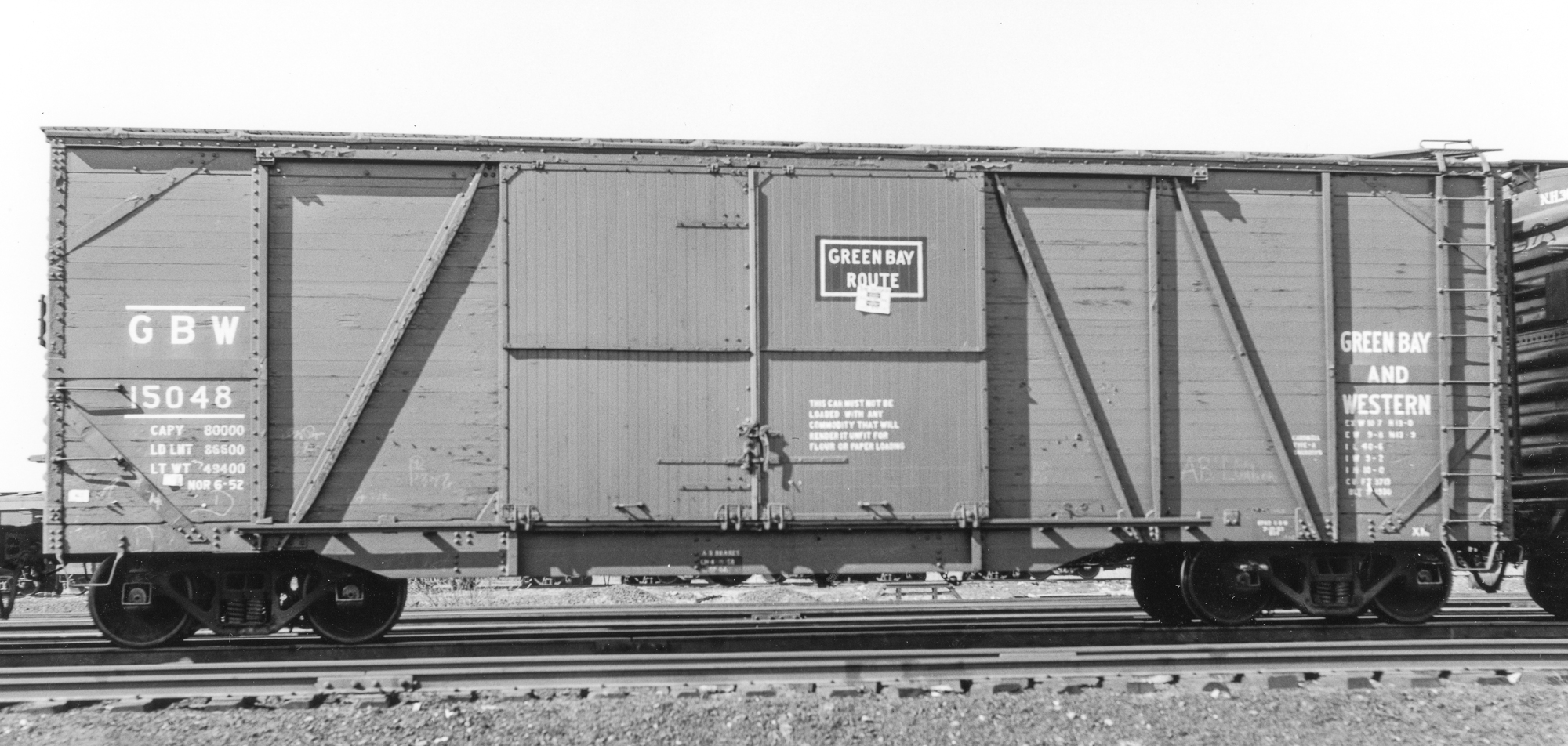
Green Bay & Western Single Sheathed Automobile Cars

April 12, 1954, Muscatine, Iowa, Rich Wilson photo, John Harker collection, Remembering the Rock Island facebook group files*

Awhile back, I posted about some Milwaukee Road forty and fifty-foot single sheathed cars. I hinted in that post that in addition to kits for the fifty-foot cars, I also was entertaining the forty-footers. Since then, I have done some pattern work for the sides of the Milwaukee cars, as I have drawings for both the 40 and 50-foot cars and there are a lot of similarities. 

Feb. 23, 1954, Cedar Hill Yard, New Haven, Col. Chet McCoid photo, Bob's Photo

Recently, an image popped up online that had me go looking through my photos to see what I had on the Green Bay & Western's single sheathed auto cars. The GB&W car in the image made me think "Milwaukee" and I wanted to see if my instincts were on the money. I was correct, but there is a very interesting twist. The GB&W cars were built at the same time and by the same builder as one of the Milwaukee's group of cars: the Bettendorf Co., circa late 1929 to early 1930. The GB&W received 50 cars total from Bettendorf in 1930, assigned to series 14000-14050 and 15000-15098. Cars moved between these two groups depending upon whether they had auto loaders installed. The 14000-series cars originally had the loaders, although by the 50s there were not loaders in either group and there are no differences noted in the Equipment Registers of the time.

circa late 50s; no additional information about this image

The twist is that while the GB&W cars are identical to the Milwaukee cars dimensionally and in almost all details, the GB&W cars have the panels adjacent to the doors swapped, which quite noticeably changes the overall layout and appearance of the car sides (excepting the wood vs. steel doors, too.) An examination of the various rivets on the side sill and side sill supports illustrates that the GB&W cars used the same underframe; it's just the sides that were modified. Below is a composited image for comparison of the two sides. I have already (excitedly) worked out all the specifics to make a second side pattern to add the GB&W cars to this project, including the later single door versions, like GBW 15082 shown above.) What a cool discovery!

* from John Harker: "Rich Wilson captured this view looking to the northeast of the Milw derailment that occurred on the RI in downtown Muscatine, Iowa on Monday morning April 12, 1954. The derailment occurred about 5:00 am. This morning view shows some of the derailed cars that stretch from about Iowa Avenue by the Hotel Muscatine back to the southwest where Rich was standing. I scanned and edited this image from an original Kodak red bordered Kodachrome slide."

Saturday, April 6, 2024

New York Central USRA Design Automobile Cars


Fayetteville, NC, Oct 12, 1952, Col. Chet McCoid photo, Bob's Photo

In 1922-1923, the Michigan Central added 4,000 automobile cars based heavily upon the USRA-design steel box cars that were the de facto standard box car of the NYC System from the 20s into the 50s. They had the same rather diminutive inside height (for an auto car) of 8'7". They were delivered in three groups: NYC Lots 440-B from Standard Steel (Hammond, IN, car nos. 96000-97999,) 464-B from American Car & Foundry (St. Louis, car nos. 98000-99499,) and 465-B from Standard Steel (Hammond, IN, car nos. 95000-95499.) They had auxiliary doors with a door opening of 10 feet. They were eventually renumbered into NYC reporting marks, series 189300-190999, 145400-146999, and 194000-195498.) Most (if not all) of the cars were built with Camel-Gilroy doors, like those shown on NYC 189735, above, and some cars, like NYC 189735, shown above, had their auxiliary doors sealed, making them into box cars. NYC 146479, shown below, had Youngstown doors and also received a replacement Murphy rectangular panel roof.

Fayetteville, NC, Oct 22, 1951, Col. Chet McCoid photo, Bob's Photo

Between 1930 and 1932, The NYC increased the height of many of these cars by adding plate steel sections at the top of the sides and raising the roof. An indeterminate number also received replacement Murphy rectangular panel roofs, as well, although photos show that many continued on with the Solidsteel roofs (lacking raised panels.) The raised roof cars were eventually assigned to series 194000-195498.

Charles Winters Collection

Paul Dunn photo, R. J. Burg

These three prototype images (above and below) illustrate how the cars appeared after the modifications. Note the Solidsteel roof and two extra Murphy end corrugations on the car shown below. 

crop of "Milwaukee Road, general view of part of Galewood Yard, Chicago," Jack Delano photo, FSA-OWI Collection, Library of Congress, call number LC-USW36-619


Years ago, I built a Westerfield kit to replicate one of the cars that continued on with its original 8'7" inside height, as shown above. While Broadway Limited released a specific version of the NYC System's USRA design box cars, Westerfield is still the only way to model many variants (including the most numerous varieties.) 

Sunshine Models also produced a kit to replicate the raised roof variants. These went out of production with the death of Martin Lofton. However, Yarmouth Model Works has resuscitated this model, with one-piece body casting.


I was fortunate to have one of the Sunshine kits in my stash and decided to start building it. As it's a flat kit, one has to assemble the sides and ends and then add the roof and floor to complete the basic assembly. I did all that, following my usual process, the most important part of which is to true up the sides first (equal length and square edges... it's been awhile since I have detailed that process, so I will post about that in the next couple weeks, with commensurate detail.) The biggest hurdle, as shown in the photos above, was that the lines of the peaks of the ends did not match that of the roof. To overcome that, I finessed things into place. My approach was to glue [ACC] the roof to one half of the top of the ends and also one side. You can see in the photo of the end of the car, how the roof is attached at the left, but the right portion is raised (not yet glued.) I let the half that was glued dry thoroughly and also augmented the joint with some 0.125" square styrene on the interior of the body where the side and roof abut. I then repeated this process for the other side. This resulted in a clean and strong assembly with the underside of the roof matching the peaks of the ends. I will continue this build in a future installment.