Sunday, December 25, 2016

A little work straightening a casting

Attempt 1 - unsuccessful!
I have been slightly grounded of late after two surgeries to repair a torn retina, plus a mild heart attack this week for my ex-mother-in-law (who’s doing very well) and lengthy dental and orthodontic appointments for my son. Some of these things have just consumed time, but the retina “thing” has affected my ability to do some of my work and my ex’s mother does a lot of the heavy lifting of getting the kids where they need to be during the week. The eye situation is kind of tough when most of what you do centers around discerning details and either writing about them or recreating them in scale!

One thing I did was to pull out a Sunshine Models PRR F30A kit to scan the side to use as part of the process of creating decal artwork. I had to clean up the main car casting (literally a casting as the prototype used a cast steel underframe with integral stake pockets and other details!) In doing so, I noticed that the portions of the car between the ends and bolsters had a noticeable droop. I did what I usually do and put the casting on a piece of glass and put it into an oven that had been preheated to 250 degrees and turned off prior to putting the glass and casting into the oven. The casting softened, as they usually do. I put the “weights” shown in the photo on the casting until it cooled* (the graphic at the bottom of the page illustrates the relative structural strength of shapes and displays while deep side sills and center sills are great at provide support to the car body or loads.) All great!

Well, when the casting cooled, I noticed that the opposite of my goal had occurred. While the ends were now flat, the center of the casting had developed a noticeable droop, making the car look sway-backed. Normally, a flat car model would have solid center sills to straighten things or I could insert a piece of square steel or brass to get things straight. However, this car is an unusual prototype and the center sills are segmented, as opposed to being two single longitudinal pieces between the bolsters, and not as solid as the side sills, meaning that depending upon them to aid in straightening the car body was an uncertain proposition. 

I reheated the casting and while it was still “soft” I used my drill bit box and one of my “weights” to try to remove the sway-back curve. I tried this several times to no avail. The casting seemed to have memory of the swayback shape. 

Attempt 2 - unsuccessful!
I resorted to something that engendered greater risk, but given that the heating and flattening method was not working, was a risk worth taking and if it failed, I could always perform the heat and flatten method to return to the previous shape. I held the center of the casting under extremely hot tap water and after I knew that the casting had become slightly pliable, I applied force with both hands to bend the casting to straighten the center portion. I then changed the water to simple cold tap water and held the casting under until it hardened. The method finally yielded the results I was seeking…. or mostly. There is still a trace of a bow on one side, but it is hardly noticeable and I am hopeful that when the deck is glued in place it will provide enough stability to pull things even more into shape.

As always, your mileage may vary.

I will be doing a full writeup on this car, although where I will post it and how is TBD.

Happy Holidays


*no, the weights do not deform the casting. If you put weight on to a relatively structurally solid piece of a casting, it shouldn’t sink or deform from the weight. Now I’m sure if you heat the casting excessively and use a lot of weight, I would be proven wrong, but I try to get things soft enough and only use enough weight to apply the proper pressure. Also, see the graphic to understand a simple property of structural integrity.

Relative structural strength

Monday, December 5, 2016

Atlas/Branchline undecorated Box Cars

P116 - Gulf, Mobile & Ohio 35200-series automobile car

I have received several inquiries regarding Branchline postwar AAR box cars kits from Atlas to be used as fodder for Speedwitch conversions. Here are some links, in no particular order or level of importance:

Atlas/Branchline Undec postwar AAR box car
HO Branchline freight car kits
Contact Atlas
Atlas Postwar AAR cars with 7' door opening - current

Also, Bill Welch provided the following:

"The stock # for the 6-ft door Undec is 20001384

Their website ordering is difficult to navigate, I think."


Customer service person is:Steve MillenbachCustomer Service ManagerAtlas Model Railroad Co908-687-0880 Ext 7147smillenbach@atlasrr.com


I believe that Steve can help with any questions about obtaining the kits.

The Speedwitch subjects that use these cars are as follows:

Parts set P108 - Erie early Postwar AAR Box Cars
P110.1 – Southern Postwar AAR Box Car Parts Set – Superior Door
P110.2 – Southern Postwar AAR Box Car Parts Set – Improved Youngstown Door

P113.1 – Louisville & Nashville Postwar AAR box car, Youngstown door


P115 - Pittsburgh & West Virginia Postwar AAR box car

Sunday, December 4, 2016

Southern gondola, part two

A long time ago, I posted about some tips to build the Speedwitch Southern gondola kit. I have done some additional work on the brake gear and want to show how I tackled things. I tend to deviate from the instructions, even on my own kits, and this car is no exception. The details follow. First, I do not have a brake arrangement for this car. I do for a similar series of Southern low-side gons built at about the same time. I used that along with prototype photos to arrive at what you see here. I cannot declare that it is 100% accurate, but it works for me.

I added the main three components: cylinder, reservoirs, and AB valve (pre-drill these first if you will be adding wire to simulate the piping). The cylinder uses a resin bracket and was attached to the face of the center sill. The AB valve was attached to a "platform" that spans the two cross members. The reservoirs were secured with brackets created from 1x4 and 1x12 strips that simulate the steel parts to which the reservoir lugs were bolted. I added nut-bolt-washer (NBW) and rivets (from an Athearn snow plow, although Archer rivets would do, as well.)

With the main components in place, I used 0.010" wire to represent the piping between the AB valve and the cylinder and reservoirs. This required some bending, fitting, and cutting to get things right, followed by securing the wire in place with ACC. I use fine, round-nose beading pliers to make these bends. With the main piping in place, I added the dirt collector to the AB valve, after first drilling it to accept the pipe from it to the train pipe. This pipe is larger, simulated with 0.015" wire, meaning the corresponding hole in the dirt collector needed to be larger. My technique is to first drill a hole with a no. 79 bit and then "open" the hole with a no. 77 bit. As I did not model the actual train pipe, the 0.015" wire runs from the dirt collector to the floor of the car, as shown.


With the piping in place, I added the brake levers and rods. The levers were created from 1x8 strip styrene, trimmed to shape using a single edge razor blade. The main lever rests in the clevis (part no. 29 on the Tichy AB brake set) extending from the cylinder. The clevis opening is actually about 0.020" wide so I always add a little .010x.030 shim at the end of the lever so that it nestles snugly into the clevis. For the bracket for the dead lever, I used a piece of leftover flat brass from an etched metal parts set. I created a u-shaped end to accept the brake lever and added two bends to allow the lever to be offset from the center sills once the bracket was glued to the face of the center sill.


With the levers in place, I added the brake rods. My technique is to add a Tichy turnbuckle to the end of a piece of 0.012" wire. One end of the turnbuckle is removed so that the resulting piece looks like a clevis. I slide these clevises over the 1x8 styrene levers and mark the wire to create bends and measure distances for cuts as I go. The turnbuckles "hold" the wire in place over the levers, allowing me to make my measurements for bends and cuts. I use a black Sharpie to mark where to bend or cut the wire. Once all the bends are made, the rods and turnbuckles are secured with ACC. Note that my brake rods are secured into the bolsters. Also, for these bends, I use a pair of beading pliers with "flat" jaws that result in sharp bends. More round, "radiused" bends look right for piping, but for the brake rod wire, a sharp bend works much better.

That's it. The next post about this car will show the finished model. The photo included here is of a finished model I built years ago, although it is the same car from the same kit. Also, a shameless plug: there are six of these kits left and once they're gone, this one will be closed out for good. So if you'd like one, navigate to the Speedwitch site and get one before they're gone.


Sunday, November 27, 2016

Creating more realistic ladders in HO Scale

This guest post is courtesy of Bill Welch and highlights his love of upgrading details on freight car models...
It began innocently I thought. In 2015, I made the rounds of Cocoa Beach-Prototype Rails, Collinsville and Lisle (now the Chicagoland RPM) with a presentation entitled Xxtreme Modeling. In this presentation I spotlighted a model of one of the Tennessee Central’s (TC) steel box cars where I claim I improved several details including the InterMountain styrene ladders included in a resin kit from WrightTRAK, using Plastruct 0.010" styrene rod. (Grandt Line also makes 0.010" styrene rod but it is gray; Plastruct’s rod is white making it much easier to use for making new ladder rungs.) Then in late 2015 it became apparent that with the aid of my friend Andy Carlson, through his relationship with InterMountain (IM), I would be able to acquire more Red Caboose X29 and 1923 ARA kits. (The Red Caboose molds are now owned by InterMountain.) Given the possibility I could add to my stash of these kits, I decided I would finally build the several models I wanted based upon these kits. Meanwhile, I did much hand wringing because I realized I had not purchased any undecorated Branchline 40-foot Postwar AAR steel box car kits and was caught napping when they sold their line of freight car kits to Atlas. I wanted several of these to build for the various Ya’ll Road owners of these cars. Through friends and the Atlas website, I have been able to acquire enough kits to build the models I want and I have started working on a couple of Branchline kits (A&WP and WofA). I am also working on two Atlas 1932 ARA kits (Erie and M-I) and two InterMountain AAR 1937 Modified Kits (Southern and KO&G). So I guess that 2016 is my “Year of Styrene faux Steel" (Now clearly stretching into 2017, hah).
Photo 1
Okay enough background, now onto the subject of improving kit ladders. I have been scratchbuilding ladders now for several years when it is warranted. Especially with wood sheathed cars ladders tended to vary. This is how I became comfortable using the 0.010" styrene rod. The TC model (photo #1) was the first time I used Kadee’s very fine bracket grabs. (Yarmouth Model Works sells a drill template for these.) Once these were mounted on the car I knew the IM ladders furnished in the kit would not do with their now visually heavy ladders rungs or treads. Leaving the ladders on their sprue for stability and strength I used sprue nippers to cut off the molded-on treads (photos #2 & 3). 
Photo 2
Photo 3
I don’t remember now but I may have also used them to pinch off the bolt detail: Just as likely I used a trusty Single Edge Razor Blade (SERB) to do this. I used the SERB to cut the rod into several small sections and proceeded to glue the rod onto the stile using liquid Testors and a small brush, locating them using whatever vestige of the molded-on treads still existed. (photos #4 and 5)  
Photo 4
Photo 5
This goes pretty quickly and it is not difficult to get most of them in place at 90°. Where I miss getting them straight, it is easy to go back and wet a joint with Testors to loosen it and get it straight. I let the ladders dry overnight and then used my nippers to cut the excess rod. Once the model was painted I was very pleased with the result. (photos #6 & 7)
Photo 6 
Photo 7
Whenever possible, especially with something like steel cars of a standard design, I like to build two or more models at a time so that I can do the repetitive steps concurrently. Detailing underframes and building the brake system two-at-a-time is faster than one-at-a-time ultimately for example. This certainly applies to modifying kit ladders so I am working on several sets currently. I decided to change my approach a little bit, cutting the treads off at an angle so as to leave a little nub of styrene (photo #8). 
Photo 8
These nubs give me something to aim at when putting the bits of rod in place and also give the rod sections a small base of styrene, making a solid joint. This way some of the bolt detail on the stiles remains. The downside is that I need to cut each section of rod to the same length. Photos #9, 10 and 11 show the result on a set of B&O 7-rung ladders.
Photo 9 - the molded-on treads compared to the new 0.010" treads
Photo 10 - a completed ladder
Photo 11 - the new ladder on the model
Atlas makes things a little harder as the detail parts in their kits come cut from the sprues so I had to improvise a way to hold them steady while worked ladder for their 1932 ARA steel boxcars. Taping their ladders to metal ruler (photo #12) made it easy to hold them rigid yet the metal meant the ladder would not accidentally get glued to something. Photo #13 shows what the improved ladder looks like on the car side.
Photo 12
Photo 13

Photos #14 and 15 show a set of ladders for a Maine Central 1923 ARA boxcar with new treads in place with their mounting straps in place also. I am going to wait until I am ready to glue them in place to trim the ends and cut them from the sprue

Photo 14
Photo 15
Photos #16 and #17 show Red Caboose X29 and InterMountain AAR 1937 Modified kit ladders, respectively.
Photo 16
Photo 17
Photos #18 and #19 are Branchline Postwar AAR kit ladders in process and completed. This kind of work takes a little more time but for the present I like the result. You must decide for yourself if you like the results.
Photo 18
Photo 19

Thursday, August 18, 2016

Adobe Lightroom for Model Railroaders

During my clinic at the RPM in Collinsville, IL (St. Louis) this past weekend (August 12-13, 2016) I mentioned that I would post a link to the presentation file. The file can be reached by clicking here.

It bears mentioning as many times as possible that if you are viewing the file separate from the live presentation at the St. Louis RPM, there was a companion “ride along” demonstration showing Lightroom’s capabilities directly from Lightroom that is absent from the file. Without that, some material presented may not be entirely clear or may seem too simplistic. Please consider attending a future RPM to see the “Full Monty”.

Monday, April 4, 2016

Interesting tarp cover on a gondola


I have seen plenty of photos of tarped loads on flat cars, usually covering equipment. However, I can't recall seeing a gon with a tarp. I'm certainly not saying this photo is unique, but given the number of photos I have seen, this one stood out. It would make an interesting and relatively easy thing to recreate. I'm leaning towards a microfiber cloth dyed to simulate the canvas tarps of the late Steam Era. I think it's worth a try. When I do it, you'll see it here.

The gon is PRR 337254, a GRA, reweighed in March, 1950 at the Rose Lake, Illinois, eastbound shops on the Pennsy.

The subject of the photo was a New Haven I-4 Pacific in the Hartford Yards, but this is far more interesting, so I zoomed in and cropped to show all of the gon that I could. All three cars can be modeled in HO. The gon can be replicated using the Westerfield kit, the Texas & Pacific automobile car can be built using an MDC single sheathed auto car (read about how in Prototype Railroad Modeling, Volume 3) and the Pere Marquette auto car can be built from Speedwitch kit K111 (wow! two Speedwitch plugs in one sentence!)

Wednesday, March 23, 2016

Ladders... arrrggghhhh!

The "completed" ladder prior to trimming the top and bottom to length. but with all other detailing added
One of the great frustrations of marketing resin kits is trying to maintain consistency even as the components that are needed to produce kits come and go. Perhaps the ultimate manifestation of this is ladders. There have only been a few choices for ladders even in the best of times. However, with the unavailability of the Branchline parts and the demise of the Details West 8-rung ladder, a huge void has opened in the ladder aftermarket. When you design a kit with a specific ladder in mind, it can be crushing to be unable to obtain that part.
The basic ladder frame with grooves and spacers, awaiting the addition of the rungs
Etched ladders are an option, but I intensely dislike the two-dimensional look of them, for both the rungs and the hardware to attach the rungs to the stiles. The rungs look flat and the hardware is either flat or absent. (Note: etched stiles with grabs are a great way to replicate Wine ladders, so etchings are not without some applications, in my opinion.)
After the addition of the first rung, but prior to the removal of the first spacer
With these obstacles in mind, I have decided to try a new approach. My next kit incorporates cast resin ladder parts with grooves for the rungs. The rungs are created using either 0.010" or 0.012" wire that is glued in the grooves. The ladders are "pre-spaced" so that the only necessity is to cut away the spacers as the rungs are added. Once the basic structure of the ladder is complete, a "face" with the appropriate detail is added to finish it off.
Three rungs in place and one spacer removed
Yes, this entails extra work. That's the downside, although it takes less than ten minutes to make a ladder and about five once you get the hang of it. The upside is that the detail looks good, the rungs are durable, and the spacing is exactly correct for the prototype.
After removal of the second spacer
I'd love to hear others' thoughts either in theory or after you have a chance to give it a try. These will debut with the Ann Arbor single sheathed box and auto cars.
Fourth rung added and third spacer removed

Six rungs down, one rung and one spacer to go!
All seven rungs in place, spacers removed, awaiting the addition of there "face"

Thursday, March 10, 2016

It's still magical

Pacific Fruit Express R-30-14 32983 from the Michael Urac Collection
I spent most of today in a darkroom, printing photos from the Michael Urac Collection as I am diligently working to get another volume of Focus on Freight Cars put together. It is the first time I have printed photos from negatives since my last year of high school. In a word, it was magical. I had forgotten about how exciting it is to put the paper into a tray of developer and wait in anticipation until that blank sheet springs to life as a photo. 

How you may ask, did I do it, given that I am smack dab in the middle of moving? I joined a community photography center - PhotosynthesisCT. If you have old negatives, be they of freight cars or anything else, I urge you to see if you have such a resource in your community. Alternatively, you could also break out that old Nikon and throw a roll of Tri-X into it and see what magic you can create. Go for it; it's a lot of fun...

P.S. as a little teaser, I'll let slip that the photo shown above will be in Volume 3 of Focus on Freight Cars.

Tuesday, March 8, 2016

Frogtape


That familiar harvest yellow reminds you of another brand, huh?
Many of us have come to love using Tamiya's masking tape. When used for masking paint, it creates crisp edges yet it doesn't pull up paint like many other masking tapes. It has a well-deserved reputation among modelers for getting the job done. Unfortunately, like many specialty items that we use, particularly those from Tamiya, its price carries a premium compared to the diminutive size of the rolls.


There is an excellent alternative that costs a fraction of what Tamiya does and performs just as effectively. Frankly, I think it is the same stuff. I found mine at a Sherwin-Williams paint shop, but I am sure it can be purchased elsewhere. It's called Frogtape and is marketed to interior house painters as, you guessed it, a superior masking tape that doesn't pull up the paint underneath it. I have rolls that are 24mm (0.94 in) and 36mm (1.41 in) wide, both in 60 yard lengths. That might be a lifetime supply for modeling. I highly recommend it.

Saturday, March 5, 2016

Some progress

Decal artwork for SP/T&NO F-70-6 & -7 flat cars
I had posted awhile back on the SP F-70-6/F-70-7 flat car kit from Espee Models and the PRR F29 depressed center flat car from Funaro & Camerlengo. Progress has been somewhat slowed by an impending move that is now in the process of happening. However, I did manage to get the artwork for the decals sent off to be printed. That gives me some motivation to have the cars painted and ready to be lettered when the decals arrive.

Decal artwork for PRR F29 & F33 flat cars
I also managed to get the boiler load finished and I will post that progress in the near future. It will be loaded on the F29.

Enjoy the artwork until next time. Note: these decals will be available from Speedwitch.

Friday, March 4, 2016

Starrett Tools

One of the things that can be either maddeningly frustrating or joyously satisfying is doing something that requires a tool. Cheap knockoffs of hand tools that are manufactured in Pakistan and sold at train shows for about 1/20th the price of their American, Swiss, Japanese, German, etc., counterparts are good cases in point. Yes, they are bargains, but sometimes you get exactly the price you pay. I generally steer clear of these items as the lack of quality makes their use frustrating, unless I know that it is a tool where quality is not the primary consideration.

When I am measuring or cutting and precision of the edges is paramount, I thank my lucky stars that I have these small Starrett squares. Yes, they are more expensive than most comparable items. However, they are machinist's quality and I know that the edges are straight and they line up exactly perpendicular to the edge against which they rest. It's as simple as that. No more explanation needed.

Another Starett tool that I own is the pin vise pictured here. I don't know the model number, but I believe the current equivalent in their line is the 162A pin vise. Most of us who build and detail model railroad items use small drill bits. I have and use ones that are sub-no. 80, down to about 0.0065". Ever try to put one of these or even a no. 80 bit into one of the hobby shop pin vises or a supposed jeweler's pin vise? You already know what happens. The collet can't close down enough and the bit isn't secure (or it may appear to be secure and then start to disappear into the collet once you start to drill). This pin vise securely holds even the smallest bits that I use. The other great thing is that it is extremely well-balanced and easy to use.

Give Starrett Tools a look. Having the right tool for a job can make it joyously satisfying...

Wednesday, February 24, 2016

Building the Speedwitch Southern gondola

The gon as viewed from the underside with strip added and underbody glued into the car body
The Southern gondola kits were my first efforts when I launched the resin portion of Speedwitch. To say that I tried to have my cake and eat it, too, is an understatement. I hated gondola models where there was a sacrifice in that either the interior side walls weren’t tall enough relative to the prototype or there wasn’t anywhere to conceal some weight. I was determined to make a car where the interior was “the way it should be” and you could still stash some weight. As with most open top scale models, something had to give. In this case, the “give” was the depth of the underframe. I purposely made the bolsters, crossbearers, crossties, and center sills shallower than the prototype in order to achieve a prototypical car interior and have somewhere to put some weight. That also meant that the coupler pockets were forced to sit right on the underside of the gondola floor, in a “cut-out” in the underbody. This also makes it a challenge to secure the coupler pockets. In retrospect, I probably bit off too much. I am certain there are many out there who are still trying to figure out how to build one of these successfully. What follows is what I hope will be a step-by-step guide to augment the kit’s instructions and explain one person’s path to building the car into a beautiful and operable model.
The interior with the floor attached
The initial step is to clean up the main body casting, comprised of sides and ends. My course of action was to rub it back and forth on a sheet of 220-grit sandpaper on a flat surface. I held the casting in between thumb and forefinger and rubbed the casting parallel to the line of the surface I was holding, switching the places I was holding frequently to avoid removing too much material in any one location. By “parallel to the surface I was holding,” that means that if I was holding the car side, I moved the length of the car side back and forth along the sandpaper. Conversely, if holding the end, I moved the length of the end back and forth across the surface of the sandpaper. In a fairly short amount of time, the casting “flash” inside the top of the car body became thin enough to flick away in most places. In those areas where there was still a little material holding the flash in place, I held the casting in that specific area and moved it across the sandpaper as described previously. Once the excess material had been removed, I cleaned up the top edges of the car with a sanding stick (read about sanding sticks by clicking.)
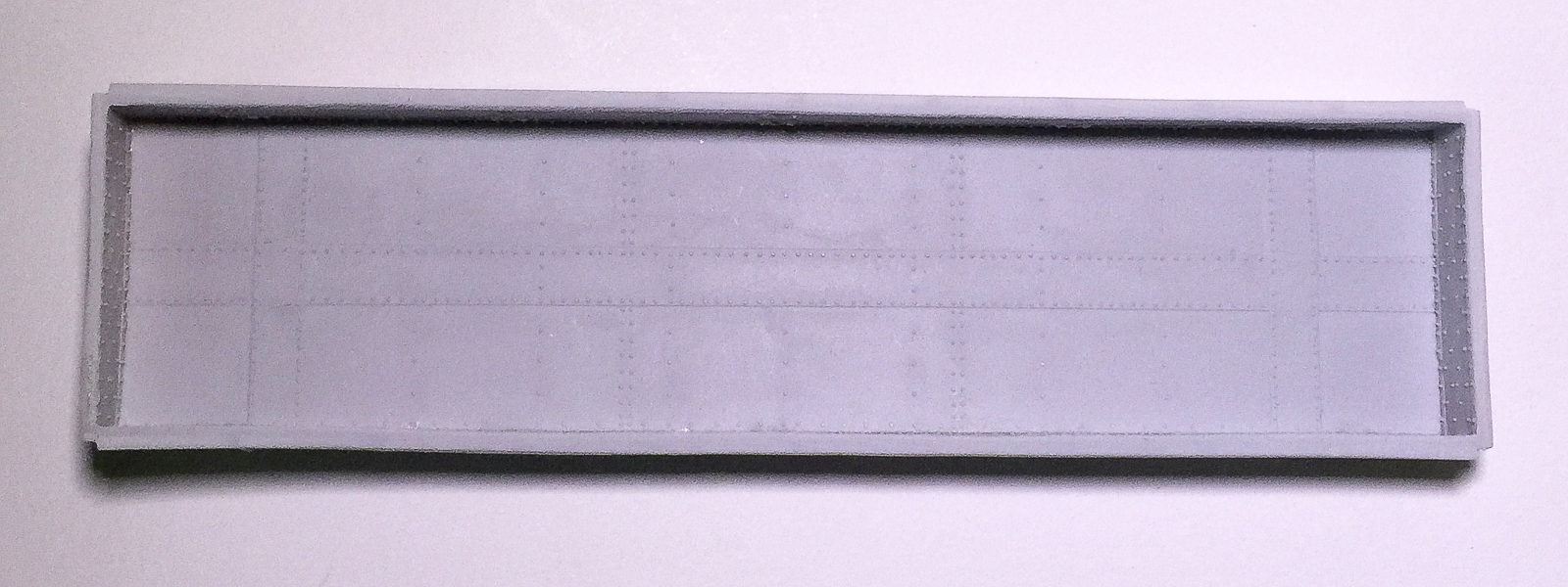
An additional view with the underbody added and the strip styrene visible at the edge
The first snafu involves the floor of the gondola. This is the part with detail on its surface that fits inside the car body and faces up when the car is on the rails. It is slightly too long (this is okay) and slightly too narrow (not okay.) It must be made marginally wider. To do this, I added 0.020” x 0.020” styrene strip to the edges (the long edges) of the casting. This was actually really easy to do. I simply laid the casting on a flat surface with the styrene strip butted against it and held in place by my finger and added a little ACC along the length using a straight pin as an applicator, moving my finger as I went, to expose the areas I hadn’t attached. It took less than five minutes. Work in small drops rather than big gobs and there will be no ACC mess or parts stuck to your work surface. It doesn’t hurt to keep checking as you go, though, to make sure your part isn’t attaching itself to your work surface. With the styrene strip added, the casting is ever so slightly too wide. A few (and I mean a few) passes of the casting over sandpaper on a flat surface should narrow things enough to fit inside the car body. To do this, hold the casting on edge and run it over the sandpaper. I always run it the same number of passes in one direction, the other direction and then flip and do the same for the other side. It’s not entirely scientific, but it does remove roughly the same amount from both sides. Do the same to shorten the ends of the casting and it should fit snugly, but not tightly, inside the car body. It fits inside the lip that is in the car body, meaning the edges of the casting you just narrowed will not be visible once the floor is glued inside the car body, if viewed looking “into” the car body, as you would if it were on the rails.
From the top, the undeframe, car body and underside of floor, and the lead weight, all with the Goo and MEK mixture added to the surfaces
Gluing the floor inside the car body is a relatively easy process. Put the car body casting on a flat surface upside down, with the top edges of the car body in contact with the flat surface. Place the floor inside the car body. You should be looking at the undetailed (“underside”) surface of the floor. If you are looking at the rivets, stop and reorient the parts. To glue the floor into the car body, there are two key things to consider: 1) work in small increments, rather than trying to glue it all at once and 2) a light pressure is all that is needed; a death grip will surely create distortions in your body casting meaning either the sides will be grossly bowed or you will induce “torque” along the length of the car body, resulting in a pronounced twist to the body. Gently push the floor into the car body so that the floor rests inside and snugly against the lip in the car body. I found it easiest to start at the center of the car and then work towards one end followed by the other. With light pressure, gently press the car body together with thumb and middle finger while applying slight pressure with the index finger to keep the floor pushed into the car body. The thumb and middle finger should be applying pressure near the edge of the car body that is closest to you (and where the floor casting is contacting the car body), not the edge that is touching the flat surface on which you are working. Applying pressure where the car body is resting on the flat surface will cause the car sides to bow, angle or cant inwards. Gentle pressure using this three-point approach with thumb and two fingers applies all the force necessary to keep things in place while you add the ACC. Add some ACC where you are applying the pressure to the joints on both sides of the car body (at the places where both thumb and middle finger are holding things together). Hold until the ACC has set up the joint. Repeat at several points until the floor is secure from the middle to one end and then repeat from the center to the other car end. As you work, make sure that the floor is nested all the way into the lip in the car body. This is your one chance to get this correct. Go slowly, checking your progress frequently. Once you have tacked everything in place, go back and add ACC along the entire floor/car body joint. If all is well, you should have the “bones” of a gondola in your hands!
The car body with weight attached and awaiting addition of the underbody casting
The next series of tasks involve addition of weight between the floor and underbody followed by gluing the underbody into the car body. For the weight, I have a large roll of 0.020” thick sheet lead that is perfect for this car (I believe it is some type of flashing for use in the roofing industry). I cut a piece of lead to fit exactly into the cavity under the floor, minus the notched areas where the coupler boxes would be located. I “painted” the underside of the car floor and the top of the weight with a mixture of Walthers Goo and methyl ethyl ketone (MEK). The MEK makes the Goo less viscous and able to be brushed on to surfaces. Once the Goo had thoroughly dried, I dropped the weight into the cavity and carefully pressed the two surfaces together, between thumb (on the lead surface) and forefinger (inside the car body). Don’t put the car body upside down on your work surface and just push on the underbody. You could damage or deform the car body. Use the thumb-forefinger technique described above as it places pressure only on the floor and underbody, not the car body. I brushed the Goo on to the still exposed lead surface and the “top” of the underbody. Once again, I let the Goo dry before adding the underbody and again pressing the surfaces between thumb and forefinger. This completed the basic assembly of the car body.

The modified coupler boxes as described in the text
The coupler and "draft gear" as attached to the model
The next task was the addition of the couplers. I used Kadee no. 153 scale couplers in the Kadee-supplied coupler boxes (“draft gear”) modified as shown. The no. 153 coupler is the same as the standard no. 158, but with a shorter shank length that was better for this car. The basic modifications included shortening the main half of the coupler box (the piece with the circular post and the “sides” of the coupler box) to butt against the inside of the end sill, and narrowing the front lip of the other half of the coupler box to fit between the draft gear opening of the car body’s end sill. Lastly, I added bits of HO scale 1x4 strip styrene to complete the “sides” of the coupler box that extend past the draft gear. The next challenge to overcome involved actually securing the coupler boxes to the car body. After some deep thought, I came up with the following plan: I would run a piece of 3/32” styrene tube through the post of the coupler box and, after drilling a hole in the floor, straight through the floor of the car. Yes, it meant a piece of styrene rod protruding from the floor of the car and subsequent sanding and cleaning up of the car floor after my “surgery”. The converse, though, is that I had a secure means to attach the couplers, beyond just gluing them (and we all know how that ends up: a coupler and lid sitting somewhere on the layout with half a train sitting uncoupled behind the coupler!) After all, the styrene rod isn’t moving and it has a hole that can accept a screw to secure the coupler boxes. That’s what I did. After everything was in place, I added a small bit of styrene rod into the center of the styrene tube visible on the top of the car floor (the hole in the tube on the underside of the car needed to remain clear to accept a 0-80 screw to secure the coupler box.) I am in the process of filling and sanding the floor of the car to clean up my mess. That’s where I will leave things for the moment. Because the tight spaces on the floor between rows of rivets dictate careful sanding, I created my own sanding tool that is a piece of styrene tube, cut at an angle at one end, with a piece of 4x10 HO scale styrene strip glued to the angled end, with a piece of sandpaper glued to the face of the strip (using the Goo/MEK solution). I had made some of these years ago for a similar situation, and I cannot remember if it is something that I created or saw somewhere else and emulated. Either way, it’s the right tool for the situation. See the photo.
Note the visible styrene rod at each end. As viewed here, all that remains is some fine sanding
The "tool" that I created for sanding the top of the floor. It consists of styrene tube, a bit of strip styrene, and some sandpaper glued to the face of the strip
All the hard work is done and I have proven that my over-engineered gondola can be built, although it takes a little planning and ingenuity. To be continued as the car is detailed and painted…
A view of the underbody