Wednesday, February 24, 2016

Building the Speedwitch Southern gondola

The gon as viewed from the underside with strip added and underbody glued into the car body
The Southern gondola kits were my first efforts when I launched the resin portion of Speedwitch. To say that I tried to have my cake and eat it, too, is an understatement. I hated gondola models where there was a sacrifice in that either the interior side walls weren’t tall enough relative to the prototype or there wasn’t anywhere to conceal some weight. I was determined to make a car where the interior was “the way it should be” and you could still stash some weight. As with most open top scale models, something had to give. In this case, the “give” was the depth of the underframe. I purposely made the bolsters, crossbearers, crossties, and center sills shallower than the prototype in order to achieve a prototypical car interior and have somewhere to put some weight. That also meant that the coupler pockets were forced to sit right on the underside of the gondola floor, in a “cut-out” in the underbody. This also makes it a challenge to secure the coupler pockets. In retrospect, I probably bit off too much. I am certain there are many out there who are still trying to figure out how to build one of these successfully. What follows is what I hope will be a step-by-step guide to augment the kit’s instructions and explain one person’s path to building the car into a beautiful and operable model.
The interior with the floor attached
The initial step is to clean up the main body casting, comprised of sides and ends. My course of action was to rub it back and forth on a sheet of 220-grit sandpaper on a flat surface. I held the casting in between thumb and forefinger and rubbed the casting parallel to the line of the surface I was holding, switching the places I was holding frequently to avoid removing too much material in any one location. By “parallel to the surface I was holding,” that means that if I was holding the car side, I moved the length of the car side back and forth along the sandpaper. Conversely, if holding the end, I moved the length of the end back and forth across the surface of the sandpaper. In a fairly short amount of time, the casting “flash” inside the top of the car body became thin enough to flick away in most places. In those areas where there was still a little material holding the flash in place, I held the casting in that specific area and moved it across the sandpaper as described previously. Once the excess material had been removed, I cleaned up the top edges of the car with a sanding stick (read about sanding sticks by clicking.)
An additional view with the underbody added and the strip styrene visible at the edge
The first snafu involves the floor of the gondola. This is the part with detail on its surface that fits inside the car body and faces up when the car is on the rails. It is slightly too long (this is okay) and slightly too narrow (not okay.) It must be made marginally wider. To do this, I added 0.020” x 0.020” styrene strip to the edges (the long edges) of the casting. This was actually really easy to do. I simply laid the casting on a flat surface with the styrene strip butted against it and held in place by my finger and added a little ACC along the length using a straight pin as an applicator, moving my finger as I went, to expose the areas I hadn’t attached. It took less than five minutes. Work in small drops rather than big gobs and there will be no ACC mess or parts stuck to your work surface. It doesn’t hurt to keep checking as you go, though, to make sure your part isn’t attaching itself to your work surface. With the styrene strip added, the casting is ever so slightly too wide. A few (and I mean a few) passes of the casting over sandpaper on a flat surface should narrow things enough to fit inside the car body. To do this, hold the casting on edge and run it over the sandpaper. I always run it the same number of passes in one direction, the other direction and then flip and do the same for the other side. It’s not entirely scientific, but it does remove roughly the same amount from both sides. Do the same to shorten the ends of the casting and it should fit snugly, but not tightly, inside the car body. It fits inside the lip that is in the car body, meaning the edges of the casting you just narrowed will not be visible once the floor is glued inside the car body, if viewed looking “into” the car body, as you would if it were on the rails.
From the top, the undeframe, car body and underside of floor, and the lead weight, all with the Goo and MEK mixture added to the surfaces
Gluing the floor inside the car body is a relatively easy process. Put the car body casting on a flat surface upside down, with the top edges of the car body in contact with the flat surface. Place the floor inside the car body. You should be looking at the undetailed (“underside”) surface of the floor. If you are looking at the rivets, stop and reorient the parts. To glue the floor into the car body, there are two key things to consider: 1) work in small increments, rather than trying to glue it all at once and 2) a light pressure is all that is needed; a death grip will surely create distortions in your body casting meaning either the sides will be grossly bowed or you will induce “torque” along the length of the car body, resulting in a pronounced twist to the body. Gently push the floor into the car body so that the floor rests inside and snugly against the lip in the car body. I found it easiest to start at the center of the car and then work towards one end followed by the other. With light pressure, gently press the car body together with thumb and middle finger while applying slight pressure with the index finger to keep the floor pushed into the car body. The thumb and middle finger should be applying pressure near the edge of the car body that is closest to you (and where the floor casting is contacting the car body), not the edge that is touching the flat surface on which you are working. Applying pressure where the car body is resting on the flat surface will cause the car sides to bow, angle or cant inwards. Gentle pressure using this three-point approach with thumb and two fingers applies all the force necessary to keep things in place while you add the ACC. Add some ACC where you are applying the pressure to the joints on both sides of the car body (at the places where both thumb and middle finger are holding things together). Hold until the ACC has set up the joint. Repeat at several points until the floor is secure from the middle to one end and then repeat from the center to the other car end. As you work, make sure that the floor is nested all the way into the lip in the car body. This is your one chance to get this correct. Go slowly, checking your progress frequently. Once you have tacked everything in place, go back and add ACC along the entire floor/car body joint. If all is well, you should have the “bones” of a gondola in your hands!
The car body with weight attached and awaiting addition of the underbody casting
The next series of tasks involve addition of weight between the floor and underbody followed by gluing the underbody into the car body. For the weight, I have a large roll of 0.020” thick sheet lead that is perfect for this car (I believe it is some type of flashing for use in the roofing industry). I cut a piece of lead to fit exactly into the cavity under the floor, minus the notched areas where the coupler boxes would be located. I “painted” the underside of the car floor and the top of the weight with a mixture of Walthers Goo and methyl ethyl ketone (MEK). The MEK makes the Goo less viscous and able to be brushed on to surfaces. Once the Goo had thoroughly dried, I dropped the weight into the cavity and carefully pressed the two surfaces together, between thumb (on the lead surface) and forefinger (inside the car body). Don’t put the car body upside down on your work surface and just push on the underbody. You could damage or deform the car body. Use the thumb-forefinger technique described above as it places pressure only on the floor and underbody, not the car body. I brushed the Goo on to the still exposed lead surface and the “top” of the underbody. Once again, I let the Goo dry before adding the underbody and again pressing the surfaces between thumb and forefinger. This completed the basic assembly of the car body.

The modified coupler boxes as described in the text
The coupler and "draft gear" as attached to the model
The next task was the addition of the couplers. I used Kadee no. 153 scale couplers in the Kadee-supplied coupler boxes (“draft gear”) modified as shown. The no. 153 coupler is the same as the standard no. 158, but with a shorter shank length that was better for this car. The basic modifications included shortening the main half of the coupler box (the piece with the circular post and the “sides” of the coupler box) to butt against the inside of the end sill, and narrowing the front lip of the other half of the coupler box to fit between the draft gear opening of the car body’s end sill. Lastly, I added bits of HO scale 1x4 strip styrene to complete the “sides” of the coupler box that extend past the draft gear. The next challenge to overcome involved actually securing the coupler boxes to the car body. After some deep thought, I came up with the following plan: I would run a piece of 3/32” styrene tube through the post of the coupler box and, after drilling a hole in the floor, straight through the floor of the car. Yes, it meant a piece of styrene rod protruding from the floor of the car and subsequent sanding and cleaning up of the car floor after my “surgery”. The converse, though, is that I had a secure means to attach the couplers, beyond just gluing them (and we all know how that ends up: a coupler and lid sitting somewhere on the layout with half a train sitting uncoupled behind the coupler!) After all, the styrene rod isn’t moving and it has a hole that can accept a screw to secure the coupler boxes. That’s what I did. After everything was in place, I added a small bit of styrene rod into the center of the styrene tube visible on the top of the car floor (the hole in the tube on the underside of the car needed to remain clear to accept a 0-80 screw to secure the coupler box.) I am in the process of filling and sanding the floor of the car to clean up my mess. That’s where I will leave things for the moment. Because the tight spaces on the floor between rows of rivets dictate careful sanding, I created my own sanding tool that is a piece of styrene tube, cut at an angle at one end, with a piece of 4x10 HO scale styrene strip glued to the angled end, with a piece of sandpaper glued to the face of the strip (using the Goo/MEK solution). I had made some of these years ago for a similar situation, and I cannot remember if it is something that I created or saw somewhere else and emulated. Either way, it’s the right tool for the situation. See the photo.
Note the visible styrene rod at each end. As viewed here, all that remains is some fine sanding
The "tool" that I created for sanding the top of the floor. It consists of styrene tube, a bit of strip styrene, and some sandpaper glued to the face of the strip
All the hard work is done and I have proven that my over-engineered gondola can be built, although it takes a little planning and ingenuity. To be continued as the car is detailed and painted…
A view of the underbody

Monday, February 22, 2016

MinuteMan Scale Models Wheel Painting Jig

MinuteMan Scale Model HO scale wheel painting jig
For several years I have used the wheel painting jig offered by American Model Builders. It is a clear acrylic laser cut jig that one glues together. When I purchased it, I appreciated its simplicity and great value. I did have one complaint: the way the jig is arranged, the wheelsets are too close together to easily allow complete painting of the two "interior" wheelsets (the ones not at the edges of the jig). However, given that it otherwise performed its intended function and there was not an alternative, I made do. I ordered this jig from MinuteMan Scale Models a couple months back and it is everything the AMB jig was, but has a greater space between each wheelset, allowing my airbrush access to easily paint the surface of all the wheelsets. Problem solved. It's nice when you can get a product that solves the problem of the product which it replaces!

P.S. MinuteMan is also the new owner of Scalecoat paints, for those of you who prefer Scalecoat

Friday, February 19, 2016

The DT&I Gondola - An Alternative

Mocked-up Proto 2000 52' Greenville gondola over DT&I prototype photo over HO scale ruler
With discussion occurring on the Steam Era Freight Car list over on Yahoo! Groups about the 41' DT&I gondolas, I'd thought I'd share something I mocked up that directly pertains to the discussion. The debate occurring is whether an old Athearn 50' gondola or a Proto 2000 52' Greenville gondola makes a better starting point for a kitbash. The Athearn route was the subject model for the Shake-n-Take project at the 2010 Prototype Rails (Shake-n-Take has its own Yahoo! Groups forum). As neither yields a 100% accurate model, it's a pick your poison prospect (there's a little too much alliteration!)
As I did not attend Prototype Rails in 2010, but still have this car on my to-do list, I had thought about it several times. My line of thinking evolved to a direction where I surmised that since Greenville built the DT&I gons and Greenville co-developed the 52' gon, then maybe there were similarities. There were enough, including the ease of modifying the Proto 2000 gon, that I settled on the Proto 2000 route and created the crude graphic shown above as a way to guide my efforts. Note that this doesn't account for any perspective issues with the prototype photo. However, by removing the middle section and a little from the end panels, a close model can be created.
I won't be tackling this anytime soon, but thought the graphic might help others while the debate about tastes great and less filling rages in other quarters. Good luck with your effort!

The devil's in the details


I love poring over the details in photos, especially finding the hidden gems in yard shots. The image above is part of larger photo of the end of the auto car (the car at left). There are a few interesting details in this photo. Some are just interesting and others are worth modeling.
The first highlighted detail is at the left, on the truck sideframe. Note the crosshatch pattern and the two lines further down the sideframe. Since the sideframes are cast, these raised details are features of the sideframe. They do not appear to offer any significant structural advantage. It is possible that they are decorative, but I have not seen anything similar before. The truck is a Dalman two-level type.
The next detail is above the truck, on the side sill. It is interesting how one leg of the grab iron is attached integrally with the sill step. This is more common than most modelers might think and is a nice detail to model on cars where it is appropriate. 
Moving to the right, note that the cast roping staple loop has cracked and broken off, with only the mounts remaining in place. I don't think this is all that common a condition, but it could be modeled. I believe that the car is a Reading composite gondola, as offered in HO scale by Funaro & Camerlengo.
The last detail is at lower right. The trucks and wheel faces were covered in the greasy soup that lubricated the axles in pre-roller bearing days. This attracted dirt, grime, and anything else that would stick. You can see a thick, coarse coating of such material below the journal box lid. This can be replicated by repeated applications of chalks and powders  with those from Bragdon being the most resistant to disappearing after addition of a flat coat to seal them. It might even be interesting to add fine granules (fine in reality; more coarse in HO or whatever scale you model) to the surface of the wheel faces and below journal lids before painting the trucks and wheel sets. I may give this a try in future. 

Wednesday, February 17, 2016

PRR F29 Load Update

In the first post about constructing a Funaro & Camerlengo Pennsy F29 depressed center flat car, I made reference to a Walthers transformer load that I was possibly going to use on this car. Fast forward a couple of weeks and in looking at the transformer once I had it in my hands, it appears to be too modern for my late-1940s dated car. So, I went back to the drawing board and became optimistic about a Bachmann boiler that is marketed integrally with their depressed center flat car. I obtained the pair for assessment.
The Bachmann boiler
The boiler is a marine boiler (I believe; I'm not an engineer or a researcher of boilers!) that scales out to about 20 feet long with a diameter of about 10 feet. The lower portion of the deck of the F29 is a little longer than 20 feet, making the boiler an ideal fit. It is going to be a perfect load for this car... with one exception. It does not weigh very much and neither does the F&C F29 (and there is no place to hide weight in the F29). The boiler is assembled, with both of the ends glued in place and I don't want to risk damaging it by trying too aggressively to pry it apart. However, I suspect I can cut a slot longitudinally in the bottom of the boiler, where it will be invisible once the boiler is loaded on the flat car, and insert lead sheet to bring the weight of the car and boiler combo up to an acceptable level.
The opposite end of the boiler
I also referred to the loading instructions for such a boiler on a flat car as contained in Rules Governing the Loading of Commodities on Open Top Cars, from the AAR, revised 1941, effective March 1, 1942. They are presented herein and will be used to create a prototypical arrangement, including the rods, blocks, and braces.
Loading diagram for boilers
The boiler also has some very prominent mold parting lines that need to be cleaned up. The rivets along those lines are also either missing or deformed. I will clean up these lines through sanding and add replacement rivets in the appropriate locations using Archer rivets. More to come as things progress...


Thursday, February 11, 2016

In praise of sanding sticks

My pile of sanding sticks and pads

In one of my dalliances with aircraft modeling, I started using sanding sticks and pads for some of the cleanup work and filing that is an inherent part of model building. While I am sure that many know about them, there may be a few out there who do not, and I feel their value means that all modelers should be aware of them and use them regularly.

While you can buy them from hobby specialists such as Micro-Mark or Squadron, you can do almost just as well, for less money, at your local drugstore. Look in the nail care section of the store.

Now for the why. You may be asking, "I already have mill files, needle files, and sandpaper. Why do I need more sanding tools?" I'm glad you asked that question. Have you ever been merrily filing something and had that, "Oh, sh.... sugar!" moment? You got a little careless or your mind wandered and you suddenly removed more material than you wanted. While the sanding sticks may not prevent all those "whoops" moments, they do prevent many. The reason is that the sanding surface is backed by a dense padding. It provides just a little "give" to the sanding surface and is less "aggressive" than a file. That translates to a little more softness when sanding and edges that are more nicely dressed or finished. In turn, that means better looking models, which is the goal.

Another benefit is the number of finishes available. There are gradations of texture from quite rough down to the equivalent of polishing-grade and everything in between. It's a range that files can't match. While sandpaper has the same range of grit or textures, sandpaper lacks the padded backing with its inherent flexibility.

What are the drawbacks? Sanding sticks and pads are not generally good at getting into tight areas. For very fine applications where you need precise control to avoid accidentally removing a specific detail, they are at a disadvantage because of their size and/or lack of rigidity, as compared to a needle file. They are also governed by coming only in a few basic shapes, all gradations of flat; conversely, files are round, curved, square, triangular, etc.

I urge you to give sanding sticks and pads a try. When I am cleaning up the edges of parts on a new kit, the first thing I reach for now is a sanding stick instead of a file.

Tuesday, February 9, 2016

A Good Point and a Decal Set

When I posted about creating decal artwork, I received a reply from Stephen Wilder, who made a very good point about the creation of accurate lettering; a point that had completely slipped my mind, but bears mentioning as it's another example of the things that are encountered in making accurate lettering. He observed that the "MA R" from my Pere Marquette lettering differed from what he had created for his Pere Marquette lettering. Yet neither of our lettering is incorrect. Often, one style of lettering will not work for a car that has constraints, such as a single sheathed automobile car (the Pere Marquette auto car has slightly condensed lettering in the road name as compared to a 1937 AAR box car or a gon) or a depressed center flat car (the "PENNSYLVANIA" on the F29  is only six inches tall). These differences must be incorporated or the lettering will not work. It's a point worth noting and I thank Stephen for making it.

I would also like to take a moment to plug the excellent decals that Stephen created: Smokebox Graphics set DF0187 for Pere Marquette freight cars. It's rare that I will rather purchase a decal set than create my own. I'm that picky. That said, I bought the Smokebox Graphics decals because the artwork is that good. They are printed by Cartograf. If you model airplanes, you know how good Cartograf decals are. I highly recommend this set.

Sunday, February 7, 2016

F&C Pennsy F29 Depressed Center Flat Car Pt. 1

In addition to the Klasing power hand brakes from True Line Trains and some photos from Bob’s and Mainline (Mike Gruber), I also brought home a Funaro & Camerlengo PRR F29 depressed center flat car from the Amherst Railroad Hobby Show. I am fully cognizant of the fact that it’s a car that is only needed sporadically. Specialized flat cars were not all that significant numerically, but they are interesting and having one to trot out once in awhile, particularly with a cool load, is a fun diversion.

The Kit
Upon opening the box, the first discovery is that there is very little to the kit. There is a one-piece “body” comprising the entirety of the car, minus the bottom plate of the underbody, castings for the trucks, detail castings, wire, and decals (although my kit was missing its decals, but no matter as I am having a set for these and the F33 printed.) As I do with all of my kits, I make a list of “missing” details, being those that my research uncovers that are absent from the kit, and substitutions, being areas where I want to replace the kit’s parts with others.
This prototype photo illustrates a few of the missing details. Photo is a crop of a photo available from Pennsylvania Railroad Photographs

The missing details include:
  • No holes in the castings (I’m referring to the steel casting on the prototype, not the resin casting; one of these castings is called out in the photo above in reference to the "halo" and hole) on the portion of the car where it angles up from the depressed deck to the “upper” deck. These holes were actually not simply holes in the castings, but actually had either small pieces of plate steel welded to the surface of the castings with circular holes through all of this, or the circular areas around these holes could have been thicker areas of the original casting. This is to be simulated using small styrene discs fashioned from 0.005” styrene, attached to the castings, with a hole drilled through.
  • There were two small pieces of steel with holes in them that were welded to the underside of the edge of the deck on the angled portion of the car. With two per section, that’s eight total to be fashioned. These do not appear to be on as-built cars.
  • There were three pieces of steel with holes in them, similar to the ones mentioned on the castings referenced above, on the “slope” of the center section of the car. In this case, I am pretty sure they were welded. Regardless, they need to be added. They appear to be offset from the angled portion of the deck, with weld beads on three edges and fourth edge left “open” presumably so that things could be anchored using the holes. Note that as-built cars do not appear to have this feature and also, interestingly, they are only on the A end of car 435496. They may have been a field modification for a specific load.
  • The retainer valves need to be added (valves rather than valve, as this car had two complete brake systems.) The brake cylinders are not modeled as they cannot be seen and they would interfere with smooth operation of the trucks.
  • The train pipe/trainline is not mentioned in the instructions, but it is a very visible element of the car, passing through the deck support angles on the left side of the car (the capital “L” Left side of the car is the left side when viewed from the B end.)
  • On the prototype, there was a support below the end sill, comprised of two “triangles”, that were on either side of the draft gear, with a strap attached to both and passing under the draft gear.
  • The cast resin trucks included in the kit can (almost) accept brake levers on the outside hangers right out-of-the-box. It’s just a matter of cleaning out the slots and creating them from styrene strip. I will do this. Note that I call these levers as, on the prototype, they had clevises and brake rods attached to them. If this terminology is incorrect and someone would like to correct me, please feel free to do so.
  • There are no route card boards in the kit. These will be added in the appropriate locations.
  • Hi-Tech Details rubber air hoses and angle cocks will be added.

Substitutions include:
  • Brass hand wheels for the brake staffs.
  • I am trying to have brass castings made of the kit’s lever-type uncoupling devices and the sill steps, in the interest of durability.
  • As mentioned before, I am producing decals.
  • The resin trucks can accept wheel sets right into the resin “journals”. However, I will drill out the journals to accept Reboxx delrin inserts. These should be significantly more free rolling. Reboxx code 88 wheel sets will be used.

Note that the instructions refer to an “under frame photo” that is not in my instruction sheet. My sheet is three pages in length so I can only assume that a fourth page was inadvertently omitted. I have included a photo herein of a Railworks model for reference.
Finally, I am awaiting a Walthers transformer kit to see if it will be an adequate load to add to the completed model.

One concession that the resin kit makes that the Railworks brass model does not is the area under the sloped portions of the deck. On the prototype and the brass model, these areas are “open” space, whereas on the model, they are filled due to the constraints of molds for resin castings. It is a good place to try one’s hand at shading to see if those areas can “disappear” on the finished model.
View of the bottom plate and the underside of the Railworks HO scale brass F29
The first step in building a resin kit is to clean up the castings and this model is no exception. However, given the design of the car, with its simple, one-piece body, it is much simpler than a typical box car. I simply filed most of the edges where I found “flash” from parting lines in the mold. I used a medium grit, cushioned board for filing nails. These are a bit more forgiving than a standard metal file and can be found at drugstores in the nail care section. The one area of cleanup that is quite different on this car is the holes in the deck. They are teardrop shaped openings. The flash in the holes was extremely thin and I found it to be extremely easy to pierce the flash with a round needle file. I entered the hole at the large end of each teardrop, cleaning that portion as the file traveled on the inward leg of its stroke and then cleaned the small end of the teardrop on the outward stroke of the file. This proved to be quick and any stubborn holes were tackled by carefully twisting a hobby knife in the opening. 
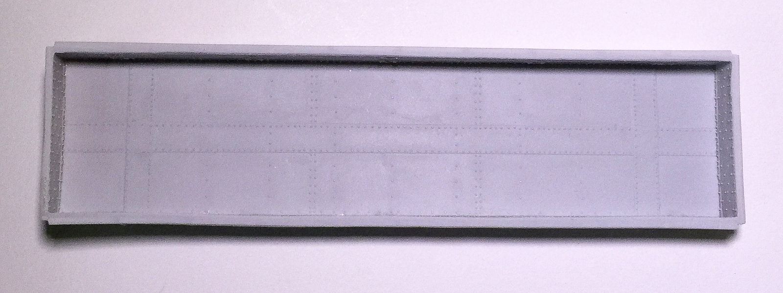
The deck after cleaning out the holes... I love photographing that white F&C resin!
I also cleaned out the holes in the bottom plate of the flat car, again using the round file. I did not glue the bottom plate in place as I plan to airbrush the space between the underside of the deck and the top of the bottom plate black. However, I did test fit and file the bottom plate so that it was a perfect fit. 

The only other prep to the car body involved flooding ACC on the inside of the some portions of the cast angles located on the slope of the car. Some of these looked quite thin in places and a little ACC could shore them up to avoid any potential damage through handling.

I wanted to have any potential problems with the trucks resolved before I tackled the finer detailing. I carefully slid the sideframe/bolster castings on a sheet of sandpaper until the flash was quite literally falling out of the castings. Again using the nail care file, I cleaned the edges of the sideframes. The openings in the sideframes needed to be cleaned. I used the round needle file for the basic work and then carefully twisted a hobby knife in areas where more material needed to be removed followed by a few more passes with the file.
Bottom view of the truck with Reboxx journal inserts and wheelsets in place

Side view of the truck side frames. Any rough edges will be smoothed when the model is grit-blasted for paint prep
With the sideframes cleaned up, I reamed the axle holes to accept the Reboxx journal inserts. I used a 0.095” drill bit that was lying on the workbench and it did the trick. Then I lined each hole and the corresponding surface of the inserts with Walthers Goo thinned with MEK. I let the Goo dry thoroughly. 
Simple diagram illustrating how the truck bolster holes were located. Note the washers with center "boss" which is where the trucks are actually secured.
While it dried, I turned my attention to locating the holes for the bolster screws, which is more challenging on a three axle truck since it is extremely difficult (or darn near impossible) to screw in a truck right under the middle axle. This means that the truck needs to be attached through a hole that is off center (who will really notice when it’s on the layout?) I know from the PRR car diagrams for the F29 that it has 39’0” truck centers. Using calipers, I measured the distance from one end of the center sill to the other. On my model, that dimension is 4.493” or 32.6 scale feet. So the center of each truck bolster needs to be 3.2 scale feet from the end of the center sill (39.0 ft - 32.6 ft / 2 [half the distance since the distance must be shared at each end of the center sill for each truck]). 3.2 scale ft = .441”. I set the calipers for .441” and, at each end of the car, marked that dimension on the “pad” where the truck hole should be located. I then marked the line that split the center sill in half along its length, where it crossed the truck hole mark that I had just made, creating an intersecting lines “crosshair”. I held the truck in place with the crosshairs centered in the middle hole on the truck bolster. Using a pencil, I traced the circle of the hole I would use to secure the trucks (I chose the hole closest to the center of the car.)

The kit includes resin castings that are effectively washers with a raised “boss” in the center. This serves to center the trucks and provide a post around which they can pivot. I glued these washers in place with ACC, using the pencil marks as guides. Once they were secure, I drilled holes using a no. 50 drill bit and added self-tapping 2-56 screws. Make sure not to drill through the surface of the car’s deck! I used shorter screws than I normally do.

I turned my attention back to the trucks. I inserted the journal inserts, carefully pressing them int the holes I had reamed. I found that Reboxx wheelsets with an axle length of 0.965” worked. The truck side frames can be carefully spread to allow the wheelsets to fit between the journal inserts. I screwed the trucks in place and was happy to see that they rolled freely.
The model as progress currently stands. Note one truck has code 110 wheelsets. I am waiting for more Reboxx sets to replace these.
The last thing I accomplished thus far was to add the couplers. I used Kadee proto couplers with the Kadee boxes. They are secured with 1-72 screws, again being careful to not drill through to the deck.

There have been articles related to the Railworks brass models published in The Keystone Modeler: TKM No. 30, January, 2006 contains a profile by Elden Gatwood and TKM No. 88, Spring 2014 contains a profile of an interesting load made by Bernhard Schroter.

More to come on the construction of this interesting car...

Monday, February 1, 2016

Springfield (Amherst) highlight!


For me, the absolute, unequivocal highlight of the weekend was one of the smallest items (HO scale) at the venue. However, it created reverberations in the prototype modeling community. Yes, Virginia, we have a Klasing power hand brake! As Teri Hatcher said on Seinfeld, “They’re real… and they’re spectacular!” They are being produced by True Line Trains. The housing and bell crank are styrene while the hand wheel is finely etched metal. 

A few notes about the parts and their application are in order. They represent the Klasing Type 650-D power hand brake with a no. 646 hand wheel. There were changes over the years, particularly to the hand wheels; the version presented here is from a late 1942 drawing. Regardless, the wheels are still similar enough that the TLT wheel can simulate the earlier (or later) hand wheels - something is a lot better than nothing! The link to True Line Trains is here. For additional reading, see Railway Prototype Cyclopedia 10.

What follows is a rough listing of cars compiled by me that used the Klasing hand brake. Where I state exact numbers not known, that means not known by me, at present, not that it can’t be uncovered (I meant to write a blog post, not the definitive work on the Klasing power hand brake!) I will try to update this as information solidifies and incorporate it into a spreadsheet for easy reference. Enjoy! A big thank you to Darren and Randy from True Line Trains for pursuing these and to Gene Green for his encyclopedic knowledge of these parts, as well as to the Klasing family for sharing the information and their passion with Gene.

Cars equipped with Klasing power hand brakes mid-1930s to early 1950s:
  • Cambria & Indiana 4700-4799 AAR Standard hopper (specific numbers with Klasing not known)
  • Chesapeake & Ohio 133000-133499 AAR Alternate Standard hopper (specific numbers with Klasing not known)
  • Chicago Burlington & Quincy HC-1 180000-180099 covered hoppers
  • Clinchfield 1932 ARA box cars
  • Duluth South Shore & Atlantic 17000-17099 Modified 1937 AAR box cars
  • Escanaba & Lake Superior hoppers 4033-4041
  • Gulf, Mobile & Ohio 32250-32399 AAR Standard hoppers
  • Illinois Central 92000-93749 (specific numbers with Klasing not known)
  • Louisville & Nashville 32000-33999 AAR Standard hoppers (specific numbers with Klasing not known)
  • Louisville & Nashville 60900-61299 Standard hoppers
  • Louisville & Nashville 69150-70399 AAR Standard hoppers (specific numbers with Klasing not known)
  • Louisville & Nashville 76150-77649 AAR Standard hoppers (specific numbers with Klasing not known)
  • Louisville & Nashville 80350-81949 AAR Standard hoppers (specific numbers with Klasing not known)
  • New Haven 31450-31499 1937 AAR box cars
  • New Haven 34000-34999 PS-1 box cars (exact nos. not known)
  • New Haven 35000-35999 PS-1 box cars (exact nos. not known)
  • New York Central 162000-163999 postwar AAR box cars (not known if entire series had Klasing)
  • New York Central 165000-165999 postwar AAR box cars
  • New York Central 868000-869999-series hoppers (exact nos. not known)
  • Soo 75800-75898 40’ steel auto cars (even nos. only)
  • Soo 42800-44098 Modified 1937 AAR box cars (even nos. only)
  • Soo 136300-136398 Modified 1937 AAR box cars (WC; even nos. only)
  • Soo 175000-series 50’ steel auto cars (WC)
  • Southern 280050-280074 covered hoppers
  • Southern 319025-319099 covered hoppers
  • Southern Pacific A-50-12 50’ steel auto cars (64100-64174 only)
  • Southern Pacific A-50-13 40’ steel auto cars
  • Southern Pacific B-50-18 1937 AAR box cars (33120-33269 only)
  • Southern Pacific B-50-21 1937 AAR box cars 83240-83739 only)
  • Southern Pacific G-50-23 Composite GS gondolas (150000-150999)
  • Southern Pacific H-70-4 94305-94404 covered hoppers
  • Texas & New Orleans G-50-17 Emergency gondolas
  • Texas & New Orleans H-70-4 4000-4049 covered hoppers
  • St. Louis Southwestern 47000-series 50’ steel auto cars (not known if entire series is Klasing)
  • St. Louis Southwestern 33700-33849 alternate center riveted box cars (exact numbers not known)
  • Union Pacific B-50-21 welded underframe 1937 AAR box cars (184200-184299 only)
  • Union Pacific B-50-24 alternate center riveted box cars (187500-188199-series; 188300-188999 [OWR&N]; specific numbers with Klasing not known)
  • Union Pacific CH-70-2 101-500 covered hoppers (specific numbers with Klasing not known)
  • Virginian 15000-15999 H-8A Emergency hoppers (specific numbers with Klasing not known)
  • Wheeling & Lake Erie 61000-61499 AAR Alternate Standard hopper
  • Wheeling & Lake Erie 62000-62649 AAR Alternate Standard hopper (specific numbers with Klasing not known)